Turbine shroud assemblies for gas turbine engines

a technology for gas turbine engines and shrouds, which is applied in the direction of blade accessories, sustainable transportation, climate sustainability, etc., can solve the problems that certain components may be difficult to meet the requirements of high temperature environments, and achieve the effects of reducing the risk of engine failure, preventing leakage of cooling air, and improving temperature managemen

Active Publication Date: 2021-02-02
HONEYWELL INT INC
View PDF33 Cites 4 Cited by
  • Summary
  • Abstract
  • Description
  • Claims
  • Application Information

AI Technical Summary

Benefits of technology

[0065]As introduced above and referring now to FIGS. 3 and 4, in one embodiment, a number of shroud segments 350 are circumferentially arranged relative to one another to form a full shroud ring. In some embodiments, one or more feather seals 450 may be inserted in between adjacent shroud segments 350. As shown, feather seals 450 may be relatively thin segments of material 452 that are partially arranged in opposing slots 454, 456 formed in adjacent shroud segments 350. The feather seals 450 may operate to mitigate or prevent leakage of cooling air out of cavities 400 formed between the shroud support structure 300 and shroud segment 350. Although one feather seal 450 is depicted between adjacent segments 350, multiple and / or partial seals may be provided. In some embodiments, the feather seals 450 may be omitted and / or other types of seals may be used.
[0066]Accordingly, exemplary embodiments discussed herein provide turbine sections, shroud assemblies, and / or shroud segments that enable improvement with respect to securing the shroud segments to the shroud support structures. The embodiments enable the formation of a cavity such that cooling air may be provided to the shroud assembly, thereby improving temperature management, operational characteristics, durability, and life span. Embodiments may find beneficial use in many industries and applications, including aircraft propulsion, auxiliary power units, electricity generation, naval propulsion, pumping sets for gas and oil transmission, automobile engines, and stationary power plants.

Problems solved by technology

The high temperature environment may be challenging for certain components with respect to durability and life span, including turbine shroud assemblies that circumscribe the turbine section and partially define the mainstream flow path.

Method used


Image

  • Turbine shroud assemblies for gas turbine engines
  • Turbine shroud assemblies for gas turbine engines
  • Turbine shroud assemblies for gas turbine engines

Examples


Embodiment Construction

[0019]The following detailed description is merely exemplary in nature and is not intended to limit the invention or the application and uses of the invention. As used herein, the word “exemplary” means “serving as an example, instance, or illustration.” Thus, any embodiment described herein as “exemplary” is not necessarily to be construed as preferred or advantageous over other embodiments. All of the embodiments described herein are exemplary embodiments provided to enable persons skilled in the art to make or use the invention and not to limit the scope of the invention which is defined by the claims. Furthermore, there is no intention to be bound by any expressed or implied theory presented in the preceding technical field, background, brief summary, or the following detailed description.

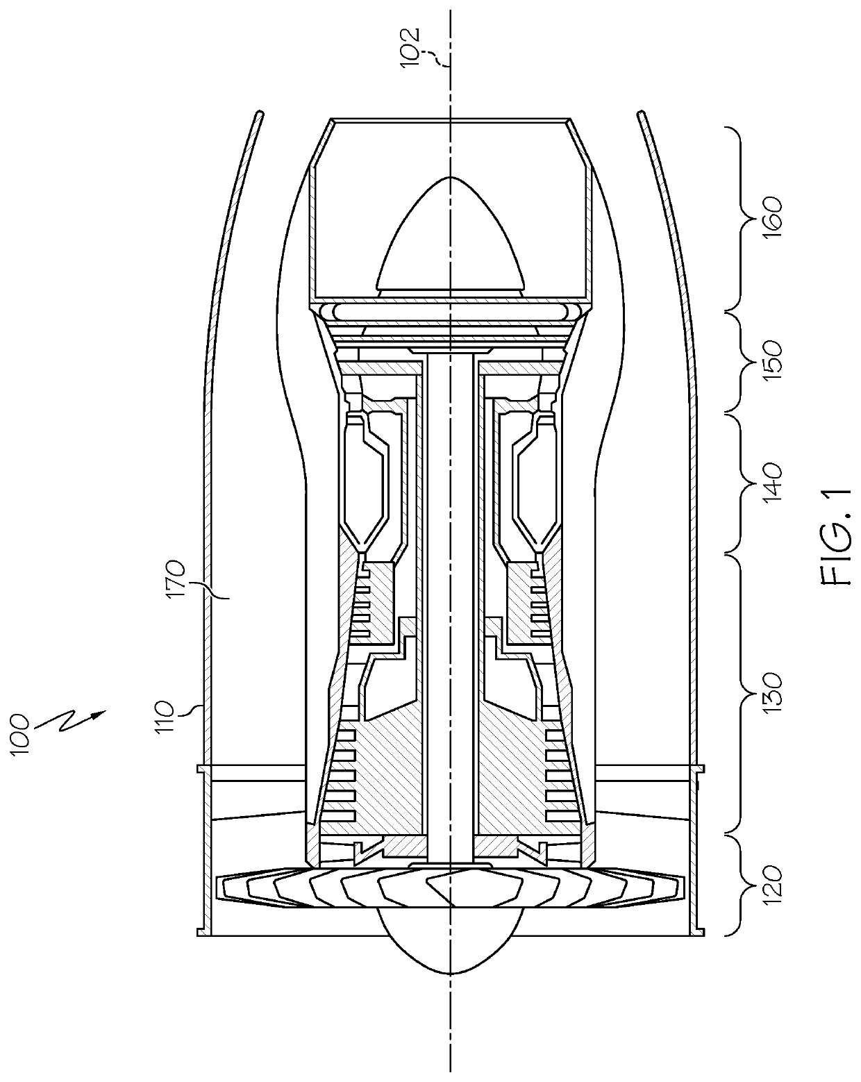
[0020]FIG. 1 is a cross-sectional view of a gas turbine engine 100 according to an exemplary embodiment. Although FIG. 1 depicts a turbofan engine, in general, exemplary embodiments discussed h...


PUM


Abstract

A turbine shroud assembly includes a shroud support and a shroud segment. The shroud support structure includes a forward support rail and an aft support rail. The forward support rail includes forward first engagement structures and the aft support rail includes aft first engagement structures. The shroud segment includes a forward segment rail and an aft segment rail. The forward segment rail includes forward second engagement structures positioned on a forward segment rail periphery and the aft segment rail includes second engagement structures positioned on an aft segment rail periphery. The forward first engagement structures radially and circumferentially engage with the forward second engagement structures and the aft first engagement structures radially and circumferentially engage with the aft second engagement structures to radially and circumferentially interlock the shroud segment to the shroud support structure.

Description

STATEMENT REGARDING FEDERALLY SPONSORED RESEARCH OR DEVELOPMENT[0001]This invention was made with Government support under W58RGZ-16-C-0046 awarded by the U.S. Army. The Government has certain rights in the invention.TECHNICAL FIELD[0002]The present invention generally relates to gas turbine engines, and more particularly relates to turbine shroud assemblies of gas turbine engines.BACKGROUND[0003]A gas turbine engine may be used to power various types of vehicles and systems. A particular type of gas turbine engine that may be used to power aircraft is a turbofan gas turbine engine. A turbofan gas turbine engine conventionally includes, for example, five major sections: a fan section, a compressor section, a combustor section, a turbine section, and an exhaust section. The fan section is typically positioned at the inlet section of the engine and includes a fan that induces air from the surrounding environment into the engine and accelerates a fraction of this air toward the compres...

Claims


Application Information

Patent Timeline
Patent Type & Authority Patents(United States)
IPC IPC(8): F01D9/04F01D25/24
CPCF01D9/04F01D25/246F05D2230/60F05D2240/11F05D2240/55F05D2240/57Y02T50/60F05D2260/201F01D11/08F05D2260/36
Inventor ZURMEHLY, LUKESMOKE, JASONKIME, KENT LPETERSEN, BLAKE
Owner HONEYWELL INT INC
Why Eureka
Try Eureka