
Catheter with split electrode sleeve and related methods

a catheter and split electrode technology, applied in the field of electrophysiology catheters, can solve the problems of difficult accurate measurement of near-field signals, increased risk of spine touching, so as to maximize tissue contact, improve accuracy, and reduce the effect of surface area

Active Publication Date: 2021-02-09
BIOSENSE WEBSTER (ISRAEL) LTD
View PDF17 Cites 0 Cited by
  • Summary
  • Abstract
  • Description
  • Claims
  • Application Information

AI Technical Summary

Benefits of technology

[0010]The present invention is directed to an electrophysiology catheter with electrodes having relatively small surface areas and an electrode configuration that maximizes tissue contact for more accurate measurement of near-field activity even when the catheter is laid sideways against tissue. The electrophysiology catheter construction simplifies the assembly and wiring of smaller electrodes on the circumference surface of the catheter distal section.

Problems solved by technology

It has been found that smaller electrodes record more accurate and discrete electrograms because larger electrodes are susceptible to detecting both desirable near-field signals and undesirable far-field signals.
The far-field signals interfere with the near-field signals, making accurate measurement of the near-field signals difficult.
With a relatively large electrode, an impedance rise from char and thrombus formation may not be easily detected because the char and thrombus are formed over a relatively small percentage of the total surface area of the electrode.
For electrophysiology catheters with more complex distal electrode configurations, such as those with multiple spine members carrying a multitude of ring electrodes, there is a greater risk of spines touching which could potentially cause the ring electrodes to short circuit.

Method used


Image

  • Catheter with split electrode sleeve and related methods
  • Catheter with split electrode sleeve and related methods
  • Catheter with split electrode sleeve and related methods

Examples


Embodiment Construction

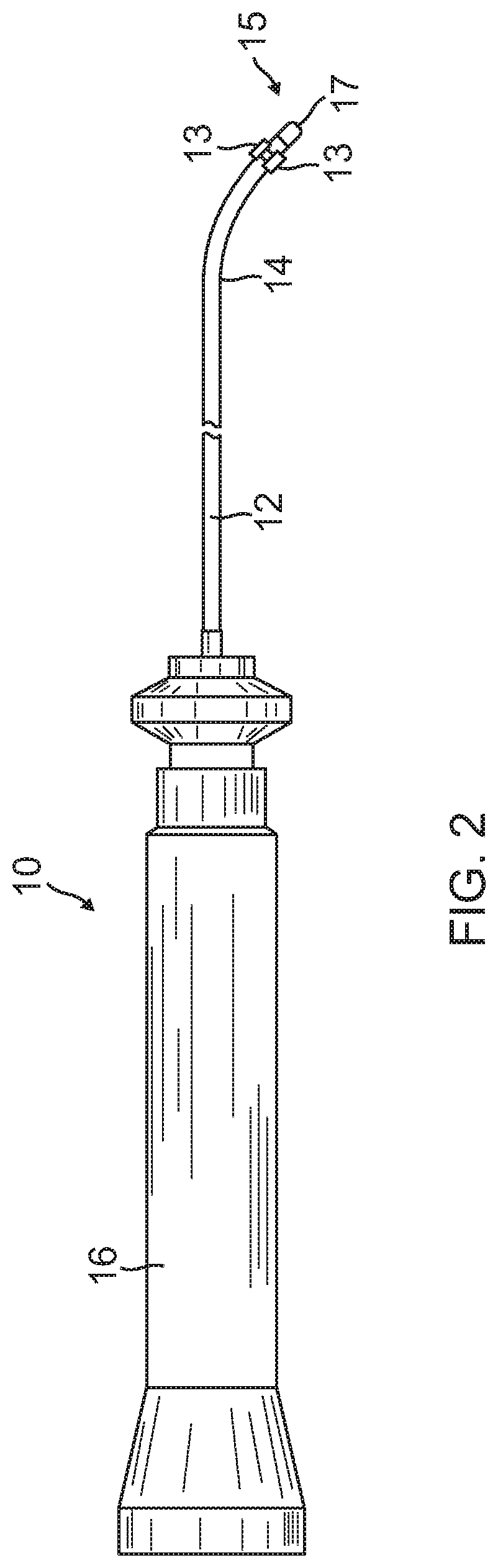
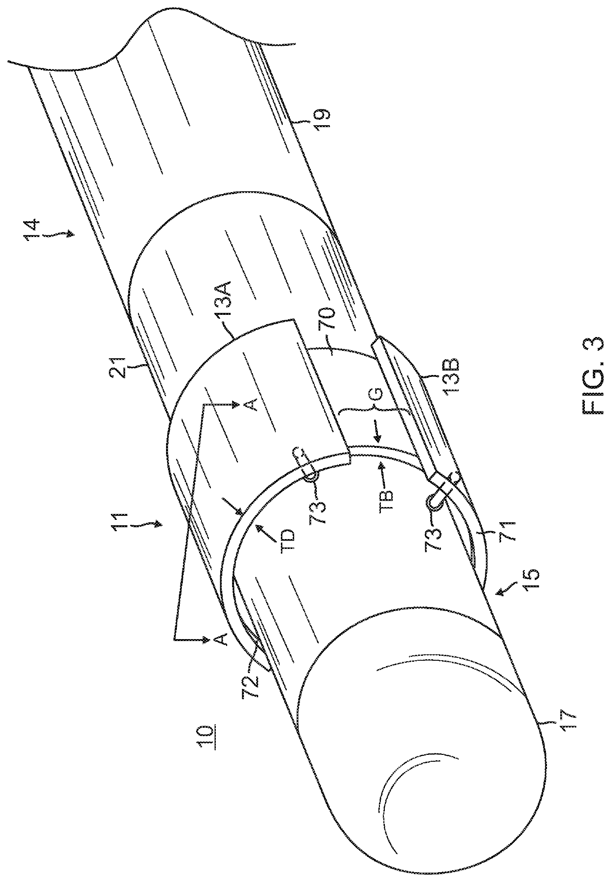
[0038]Referring to FIG. 2 and FIG. 3, the present invention includes a catheter 10 with a split electrode sleeve 11 adapted for discrete electrode tissue contact and minimized exposure to blood. In some embodiments, the catheter comprises a catheter body 12, an intermediate deflection section 14, a distal end section 15, and a control handle 16 proximal of the catheter body 12. In some embodiments, the split electrode sleeve 11 has a band 70 and a plurality of discrete electrodes 13, and the sleeve 11 is carried on the distal end section 15, proximal of a distal end or distal tip electrode 17.

[0039]The catheter body 12 comprises an elongated tubular construction, having a single, axial or central lumen 18, as shown in FIG. 2 and FIG. 4. The catheter body 12 is flexible, i.e., bendable, but substantially non-compressible along its length. The catheter body 12 can be of any suitable construction and made of any suitable material. A presently preferred construction comprises an outer w...


PUM


Abstract

An electrophysiology catheter having an electrode sleeve mounted on a distal section, the electrode sleeve comprising an electrically-nonconductive band and a plurality of discrete electrodes, the band extending circumferentially around the distal section, each discrete electrode occupying a different radial position around the band. The catheter includes a plurality of lead wires extending through the elongated body and the deflection section, and into the distal section, each lead wire passing through a respective aperture formed in the sidewall of the tubing of the distal section, each wire being connected at its distal end to a respective discrete electrode.

Description

FIELD OF INVENTION[0001]This invention relates to an electrophysiology catheter, in particular, a cardiac electrophysiology catheter with an electrode configuration that provides for more accurate and discrete sensing.BACKGROUND[0002]Electrode catheters have been in common use in medical practice for many years. They are used to stimulate and map electrical activity in the heart and to ablate sites of aberrant electrical activity.[0003]In use, the electrode catheter is inserted into a major vein or artery, e.g., femoral artery, and then guided into the chamber of the heart which is of concern. Once the catheter is positioned within the heart, the location of aberrant electrical activity within the heart is then located.[0004]One location technique involves an electrophysiological mapping procedure whereby the electrical signals emanating from the conductive endocardial tissues are systematically monitored and a map is created of those signals. By analyzing that map, the physician ca...

Claims


Application Information

Patent Timeline
Patent Type & Authority Patents(United States)
IPC IPC(8): A61B5/042A61B5/00A61B18/14A61B17/00A61B18/00
CPCA61B5/0422A61B5/6852A61B17/00234A61B18/1492A61B2017/00053A61B2017/00323A61B2017/00327A61B2018/00083A61B2018/00166A61B2018/00351A61B2018/00577A61B2018/00839A61B2018/1467A61B2018/1497A61B5/283A61B5/287
Inventor AUJLA, VISHAV MANAK SINGH
Owner BIOSENSE WEBSTER (ISRAEL) LTD
Features
  • Generate Ideas
  • Intellectual Property
  • Life Sciences
  • Materials
  • Tech Scout
  • Unparalleled Data Quality
  • Higher Quality Content
  • 60% Fewer Hallucinations
Learn More