
Peripheral vision in a human-machine interface

a human-machine interface and peripheral vision technology, applied in the field of display methods and systems, can solve the problems of pilots overloaded or distracted by other tasks, not taking note of important information, human-machine interfaces are increasingly complex, etc., to improve pilots' ability to concentrate on the actual piloting, simplify human-machine interactions, and relieve pilots of tedious manipulations

Active Publication Date: 2021-02-09
THALES SA
View PDF6 Cites 0 Cited by
  • Summary
  • Abstract
  • Description
  • Claims
  • Application Information

AI Technical Summary

Benefits of technology

[0010]Generally speaking, the examples that are provided simplify human-machine interactions and in particular relieve the pilot of tedious manipulations that are sometimes repetitive and often complex, by the same token improving his ability to concentrate on the actual piloting. These manipulations and operations often take place in emergency contexts or contexts which require a rapid reaction. The cognitive effort to be provided for driving or piloting is optimized, or, to be more precise, reallocated to cognitive tasks that are more useful with regard to the piloting objective. In other words, the technical effects linked to certain aspects of the invention correspond to a reduction in the cognitive load of the user of the human-machine interface.
[0011]The improvements and refinements according to the invention are advantageous in that they reduce the risks of human error in the context of the human-machine interaction (for example risk of deletion of critical data or of these not being taken into account, etc.). The embodiments of the invention therefore contribute to improving security and aeronautical safety (more generally of vehicle piloting).
[0012]Some embodiments make it possible to warn or to inform the pilot visually with regard to a particular event on the basis of the cognitive load to which he is subject (for example without disturbing him from his current task). By contrast, existing solutions are fixed or static in the sense that they do not take into account the cognitive load of the pilot (an audio warning may not be perceived during a high workload, for example a message or an indicator light may leave the pilot's field of view because peripheral vision may be reduced).
[0013]Moreover, some embodiments make it possible to warn or to inform the pilot visually with regard to a particular event, regardless of where he is looking. The embodiments of the invention therefore optimize the demands and the use of the pilot's field of vision.
[0015]By expanding the display methods to augmented and / or virtual reality environments, the invention allows new interaction possibilities. By contrast, the human-machine interfaces according to the avionic prior art are generally designed with respect to the (limited or even confined) display formats. New augmented or virtual interaction possibilities make it possible to redefine the human-machine interfaces themselves. For example, the user's field of view may be used optimally and more intensively. There may be actual interactive dialogue between the machine and the human, for example so as to keep a high level of attention or to optimally utilize the latter. In this case, the embodiments of the invention make it possible to increase the display surface area used or able to be used at the periphery of the field of vision, by optimizing the use of this visual zone.

Problems solved by technology

In some circumstances (for example flight context or mission type), the pilot may be overloaded with information to the point that he does not respond to requirements communicated by the avionic systems.
Specifically, a pilot overloaded with or distracted by other tasks might not note important information that the system may present to him.
The consequences may turn out to be drastic.
Moreover, human-machine interfaces are increasingly becoming more complex.
These existing solutions exhibit defects or inadequacies.
This approach has limitations.

Method used

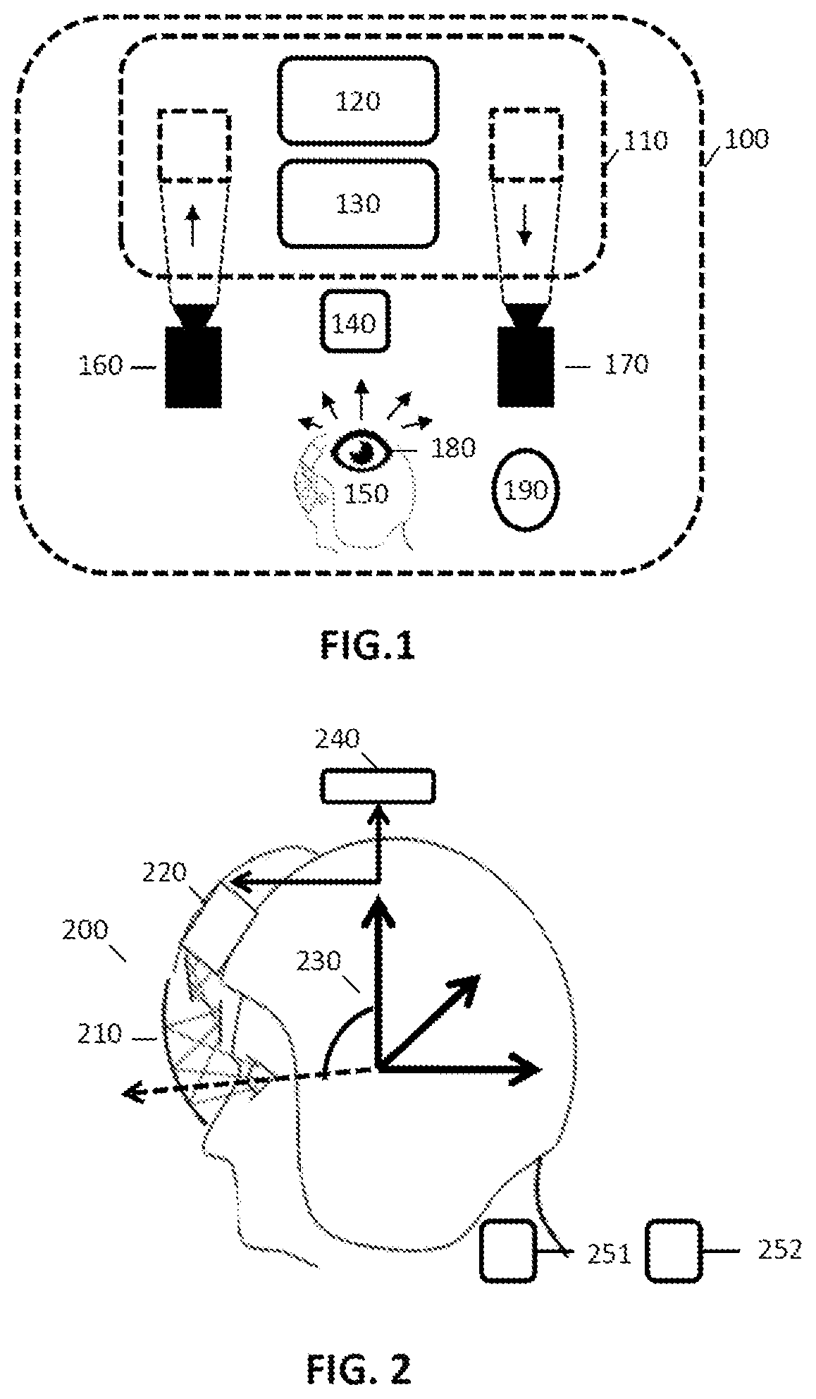
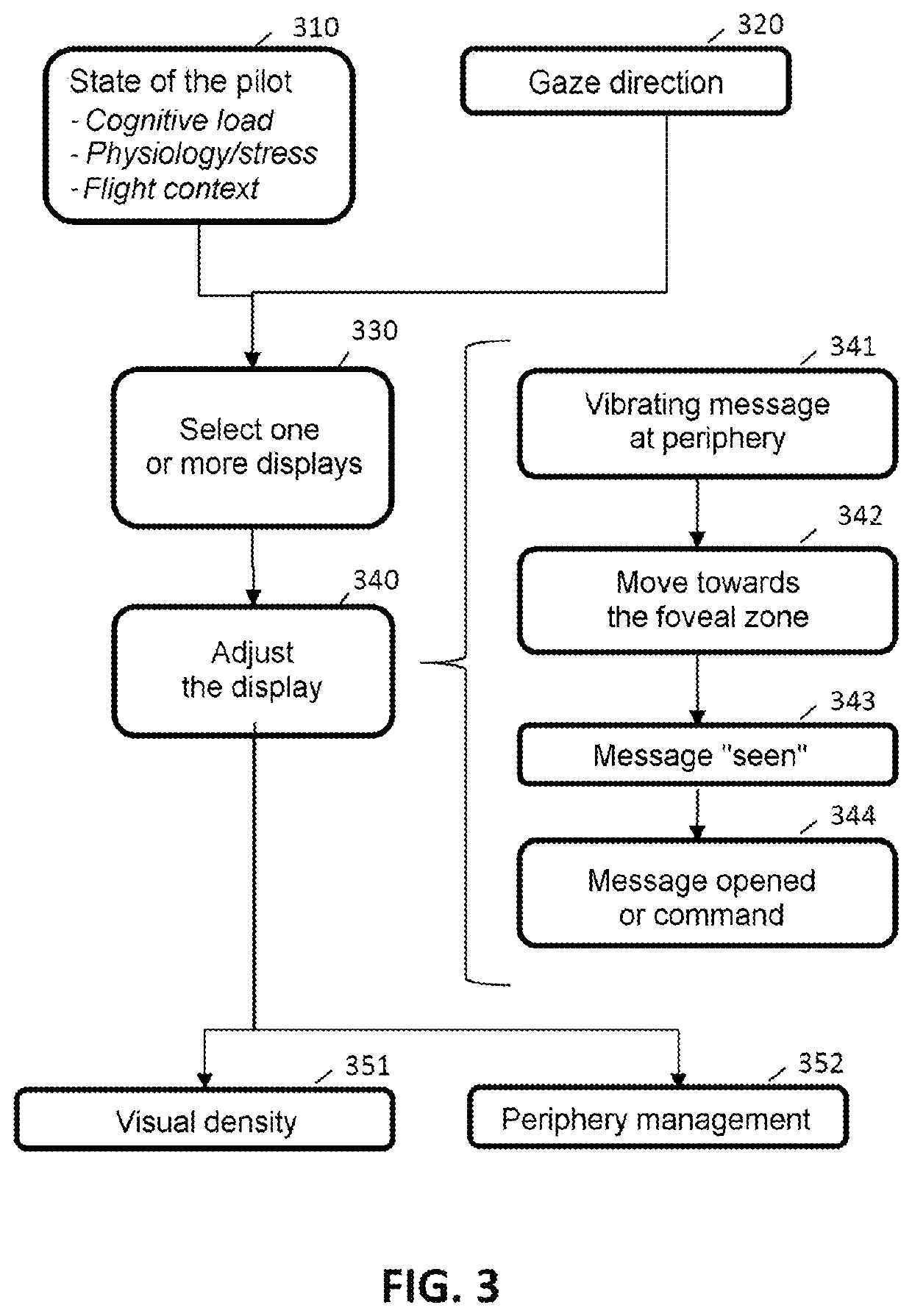
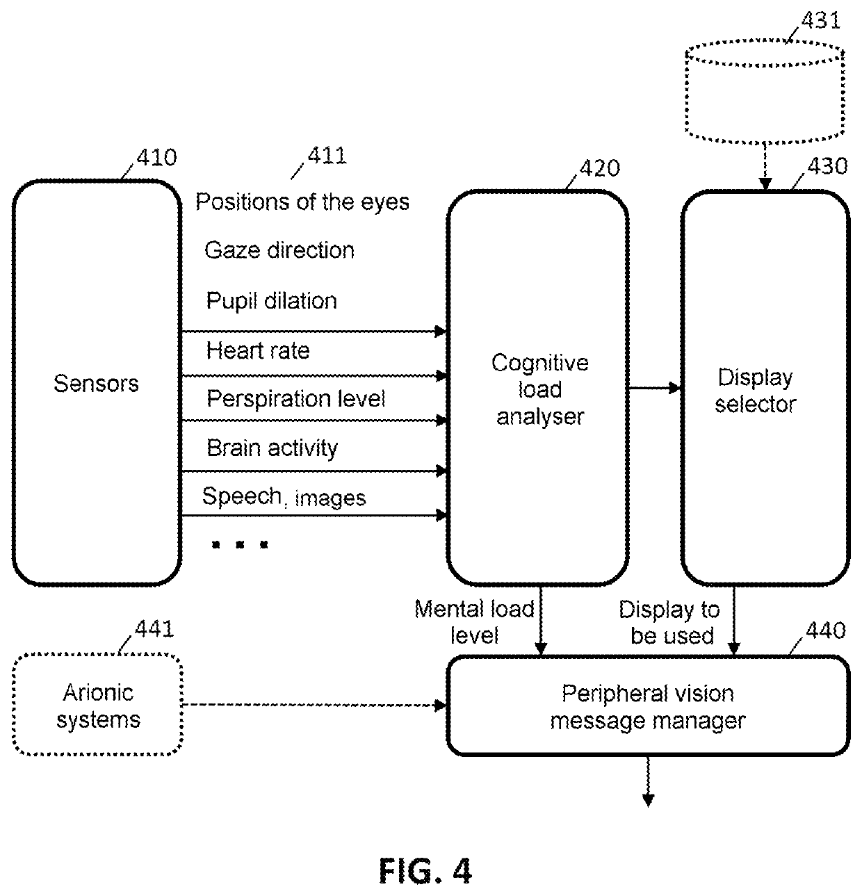

Image

  • Peripheral vision in a human-machine interface
  • Peripheral vision in a human-machine interface
  • Peripheral vision in a human-machine interface

Examples


Embodiment Construction

[0025]According to the embodiments of the invention, an aircraft may be a commercial, military or cargo aeroplane, an autonomous or remotely piloted drone, a helicopter, or any other transport means able to use a human-machine interface. The invention is not limited to aeronautical applications: the embodiments may be applicable to other types of vehicle (e.g. car, lorry, bus, train, boat, etc.).

[0026]The term “display device” manipulated by the invention denotes any display system interspersed or inserted between the visual system (i.e. the eyes) of a user (e.g. surgeon, pilot, computer scientist, etc.) and his external environment (which therefore forms a ‘visual background’).

[0027]The ‘field of view’ literally denotes the portion of space seen by an eye. An eye perceives light, colours, shapes, textures, etc. in this spatial zone. By extension, the two eyes perceive a portion of space stereoscopically. Vision may be of various types: monocular or binocular. This field of view con...


PUM


Abstract

A computer-implemented method for managing a graphical human-machine interface, includes the steps of receiving information relating to the position of the eyes and the gaze direction of a user at the interface; receiving physiological information of the user; determining a level of cognitive load on the basis of the received physiological information; adjusting the display of the interface on the basis of the gaze direction and / or of the determined level of cognitive load. Some developments describe the management of the display zones (foveal zone and peripheral zones), the selection of one or more displays, the management of the distance from the message display to the current gaze location, the management of the criticality of the messages, various graphical techniques for attracting attention, the management of the flight context in the avionic case, the management of visual density, etc. Some system aspects are described (virtual and / or augmented reality).

Description

CROSS-REFERENCE TO RELATED APPLICATIONS[0001]This application claims priority to foreign French patent application No. FR 1800125, filed on Feb. 12, 2018, the disclosure of which is incorporated by reference in its entirety.FIELD OF THE INVENTION[0002]The invention relates to the technical field of display methods and systems in general, and more specifically to that of multimodal interfaces in an aircraft cockpit.BACKGROUND[0003]In the piloting cabin of a modern aircraft, the pilot receives and manipulates a large amount of information. In some circumstances (for example flight context or mission type), the pilot may be overloaded with information to the point that he does not respond to requirements communicated by the avionic systems. In some cases, the pilot may not even perceive the stimuli. Specifically, a pilot overloaded with or distracted by other tasks might not note important information that the system may present to him. In aviation history, it has happened before that ...

Claims


Application Information

Patent Timeline
Patent Type & Authority Patents(United States)
IPC IPC(8): G02B27/01G02B27/00G06F3/01B64D43/02A61B3/024A61B3/00A61B3/113
CPCG02B27/0172A61B3/0033A61B3/0058A61B3/024A61B3/113B64D43/02G02B27/0093G02B27/017G06F3/013G02B2027/014G02B2027/0181G02B2027/0185G02B2027/0187G06F2203/011B64D43/00G06F9/451
Inventor LAFON, STÉPHANIEBAILLY, ALEXIANEDOTTE, SÉBASTIEN
Owner THALES SA
Learn More