Impacting type applicator for microneedle patch and leading end member

a technology of leading end member and applicator, which is applied in the direction of microneedles, infusion needles, other medical devices, etc., can solve the problems of difficult stably administering medicine into dermis, difficult to consistently produce appropriate load, etc., and achieve stable medicine administration and improved workability of the device that inserts a microneedle into the skin.

Active Publication Date: 2021-02-16
LABO JUVERSA
View PDF20 Cites 2 Cited by
  • Summary
  • Abstract
  • Description
  • Claims
  • Application Information

AI Technical Summary

Benefits of technology

[0036]With the impacting type applicator for a microneedle patch according to the present invention, the workability of a device that inserts a microneedle into a skin is improved, so that stable medicine administration is achieved.

Problems solved by technology

That is, it is difficult to consistently produce an appropriate load.
Thus, the microneedle of the microneedle is often insufficiently inserted into the dermis of the skin, and as a result, it is difficult to stably administer a medicine into dermis.

Method used


Image

  • Impacting type applicator for microneedle patch and leading end member
  • Impacting type applicator for microneedle patch and leading end member
  • Impacting type applicator for microneedle patch and leading end member

Examples


first embodiment

1. First Embodiment

[0059](1) Overview of Configuration of Applicator

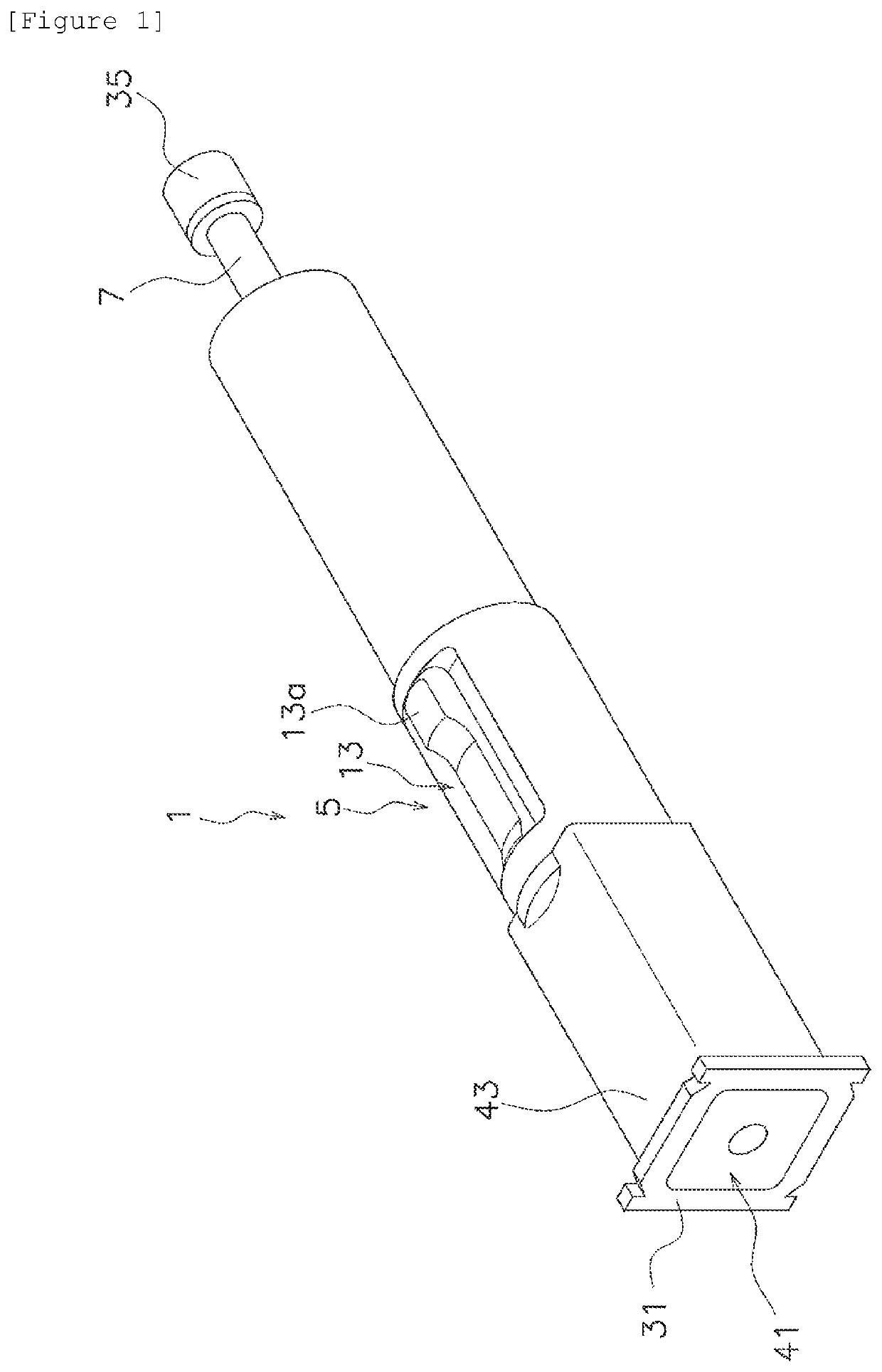
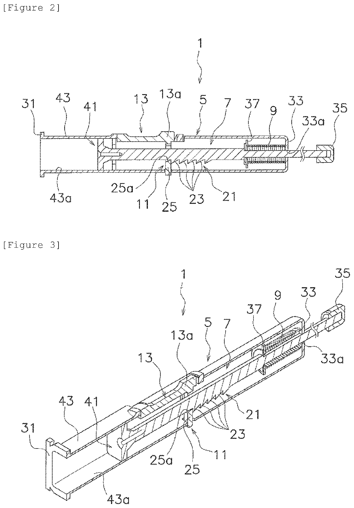
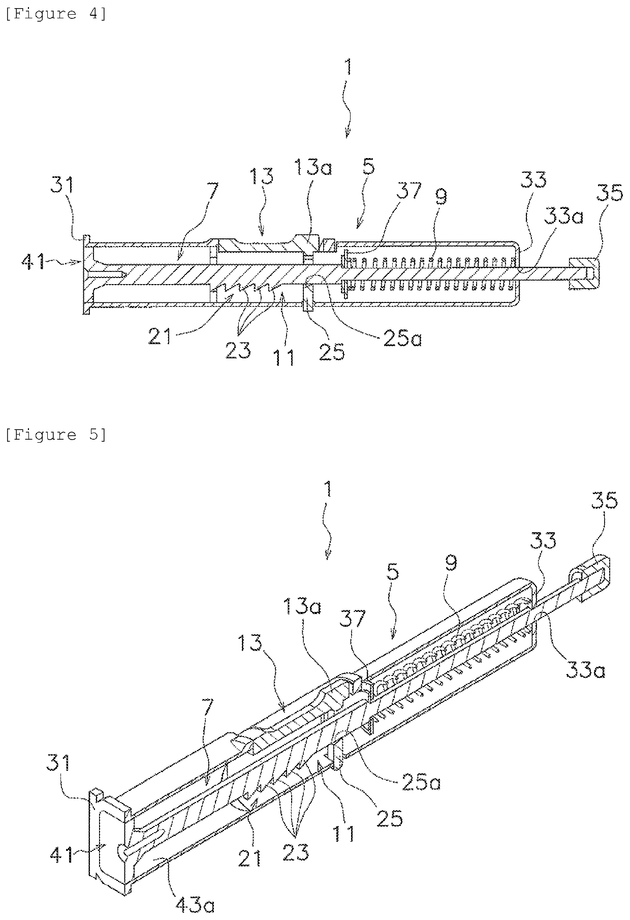
[0060]An impacting type applicator 1 for a microneedle patch (hereinafter referred to as “applicator 1”) according to an embodiment of the present invention will be described with reference to FIGS. 1 to 5. FIG. 1 is a perspective view of the impacting type applicator for a microneedle patch according to a first embodiment of the present invention. FIGS. 2 and 4 are cross-sectional views of the applicator. FIGS. 3 and 5 are perspective cross-sectional views of the applicator.

[0061]The applicator 1 is a device designed to press a microneedle patch 3 (FIGS. 6 and 7) against a skin to insert a microneedle into a dermis. More specifically, the applicator 1 can produce a biasing force high enough to pierce the microneedle patch 3 into the skin.

[0062]As shown in FIGS. 6 and 7, the microneedle patch 3 has a substrate 3a and a large number of microneedles 3b formed on one surface of the substrate 3a. The microneedles 3b are...

second embodiment

2. Second Embodiment

[0102]An applicator 101 according to a second embodiment will be described with reference to FIGS. 8 to 10. FIG. 8 is a perspective view of a leading end part of the impacting type applicator for a microneedle patch according to the second embodiment of the present invention. FIG. 9 is a cross-sectional view of the leading end part of the applicator. FIG. 10 is a cross-sectional view of the leading end part of the applicator.

[0103]The applicator 101 is a device that applies a microneedle patch 103 to the skin and has basically the same structure as the applicator according to the first embodiment.

[0104]The applicator 101 has a leading end member 102, which is attached to a leading end of a main body 105.

[0105]The leading end member 102 has a frame-shaped main body 104.

[0106]The leading end member 102 has a contact part 106. The contact part 106 is a part that is provided on the frame-shaped main body 104 and is intended to come into contact with the skin. More sp...

third embodiment

3. Third Embodiment

[0115]An applicator 101A according to a third embodiment will be described with reference to FIGS. 11 to 13. FIG. 11 is a perspective view of a leading end part of the impacting type applicator for a microneedle patch according to the third embodiment of the present invention. FIG. 12 is a cross-sectional view of the leading end part of the applicator. FIG. 13 is a cross-sectional view of the leading end part of the applicator.

[0116]The applicator 101A is a device that applies a microneedle patch 103A to the skin, which has the same basic structure as the applicator according to the second embodiment.

[0117]The applicator 101A has a leading end member 102A, which is attached to a leading end of a main body 105A.

[0118]The leading end member 102A has a frame-shaped main body 104A.

[0119]The leading end member 102A has a contact part 106A. The contact part 106A is a part that is provided on the frame-shaped main body 104A and is intended to be contacted with the skin. ...


PUM


Abstract

To achieve stable administration of a medicine into a dermis by improving the operability of a device that inserts a microneedle into a skin. An impacting type applicator (1) for a microneedle patch is an applicator that applies a microneedle patch (3) to a skin includes a main body (5), a spring expanding / compressing lever (7), a resilient body (9), a lock mechanism (11), and a piercing switch (13). The spring expanding / compressing lever (7) is movably attached to the main body (5), and the microneedle patch (3) can be attached to a leading end of the spring expanding / compressing lever (7). The resilient body (9) is a member that imparts a biasing force to the spring expanding / compressing lever (7). The lock mechanism (11) is a mechanism that locks the spring expanding / compressing lever (7) in a state where the resilient body (9) exerts the biasing force on the main body (5). The piercing switch (13) is a member that releases the engagement between the lock mechanism (11) and the spring expanding / compressing lever (7). In addition, a biasing force imparting mechanism (121) further imparts a biasing force to the spring expanding / compressing lever (7) in a state where the spring expanding / compressing lever (7) is moved toward the leading end of the main body (5) and thereby presses the microneedle patch (3) against the skin.

Description

TECHNICAL FIELD[0001]The present invention relates to an impacting type applicator for a microneedle patch and a leading end member.BACKGROUND ART[0002]The human skin consists of the cornified layer having a layered structure having a thickness of about 10 to 30 μm, the epidermal layer having a thickness of about 50 to 200 μm and the dermal layer having a thickness of about 2 to 5 mm. Of these layers, the cornified layer and the epidermis layer each have a strong barrier function and hence it is hardly expectable that a medicine having a high molecular weight is adsorbed intradermally. On the other hand, it is characteristic of the dermis layer that a dense capillary network is present in its superficial layer referred to as a papillary layer. In addition, as is known, Langerhans cells, which play an important role in immune sensitization, are present in the epidermis layer, and the early stage of the immune sensitization occurs with substances which are present in the epidermis and...

Claims


Application Information

Patent Timeline
Patent Type & Authority Patents(United States)
IPC IPC(8): A61M37/00
CPCA61M37/0015A61M2037/0023A61M2202/30A61M2205/0288A61M2037/0061A61M2205/58
Inventor NAGAI, HIROYUKINAKAOKA, RISAONO, ICHIROTAKADA, KANJI
Owner LABO JUVERSA
Why Eureka
Try Eureka