Vascular access site management system

a management system and access site technology, applied in the field of vascular access sites, can solve the problems of local trauma, catheter and/or extension tube bending, and increase the risk of kinking, and achieve the effect of stabilizing the vascular access site management system

Active Publication Date: 2021-05-25
NP MEDICAL
View PDF35 Cites 3 Cited by
  • Summary
  • Abstract
  • Description
  • Claims
  • Application Information

AI Technical Summary

Benefits of technology

[0010]In further embodiments, the system may have a valve mechanism located in the fluid path. The valve mechanism selectively prevents and allows fluid flow through the internal fluid path. The stabilization body may have an inlet body and an outlet body and the valve mechanism may be positioned between the inlet body and outlet body. The valve mechanism may be a two way pressure activated valve that deforms in the presence of a forward pressure within the internal fluid path (e.g., to allow fluid flow around the valve mechanism from the inlet to the outlet). To help support the valve mechanism within the stabilization body, the outlet body may have a plurality of support arms. The valve mechanism may deform over the support arms in the presence of the forward pressure. Additionally or alternatively, the valve mechanism may include a slit extending through it. The slit may open in the presence of a back pressure within the internal fluid path to allow fluid flow through the slit and from the outlet to the inlet. Additionally or alternatively, the pressure required to open the slit may be above the venous pressure of the patient.
[0014]The method may also include connecting the outlet of the stabilization body to a vascular access device, and placing the stabilization body on the patient. The stabilization surface may stabilize the vascular access site management system on the patient. Once on the patient, the method may then rotate the sleeve portion of the flow housing relative to the stabilization body to a second position. The flow path in the pathway portion may be fluidly disconnected from the inlet of the stabilization body when in the first portion, and fluidly connected to the inlet of the stabilization body when in the second position.
[0015]In some embodiments, the system may include a valve mechanism located in the fluid path. The valve mechanism may have a slit through it and may selectively prevent and allow fluid flow through the internal fluid path. For example, the valve mechanism may deform in the presence of a forward pressure within the internal fluid path to allow fluid flow around the valve mechanism from the inlet to the outlet. Additionally or alternatively, the slit may open in the presence of a back pressure within the internal fluid path to allow fluid flow through the slit and from the outlet to the inlet. The vascular access site management system may have a first and second securement portion located on the underside of the stabilization surface. The first and second securement portions may secure the vascular access site management system to the patient.
[0017]The device may also have a first engagement element located on a surface of the vascular access site management system. The first engagement element may engage with a second engagement element located on the medical implement to couple the medical implement with the vascular access site management system and position the distal tip at a predetermined longitudinal position in the flow path (e.g., when coupled to the vascular access site management system). The distal tip may interact with the valve mechanism when in the predetermined longitudinal position to allow passage of the medical article into the vascular access site management system. For example, the distal tip of the medical implement may at least partially open the valve mechanism when in the predetermined longitudinal position. In some embodiments, the valve mechanism may be supported in the vascular access site management system such that the longitudinal movement of an outer portion of the slit toward the first end is minimized.
[0023]Further embodiments may include a tube having a first end and a second end. The first end may be fluidly connected to an inlet of the vascular access site management system and / or there may be a needle free connector located at the second end of the tube. The upper portion may include a male luer lock connector that may be connected to a catheter / or alternatively an access device such as a needleless connector. Additionally or alternatively, the upper portion may have a contact surface within the flow path. The contact surface may contact an outer surface of the medical implement during connection of the medical implement to prevent further longitudinal movement of the distal tip within the flow path and / or radially align the distal tip with the flow path. The upper portion may also have a crushable or deformable guide rib within the flow path to keep the distal tip concentric within the flow path during connection of the medical implement.

Problems solved by technology

Tapes and adhesive film dressings can be problematic in that they may not firmly secure the catheter in place, which can lead to local trauma to the vein and a medical condition referred to as phlebitis requiring removal of the catheter.
Additionally, in some instances, the manner in which the tape is applied and the positioning / location of the catheter and / or extension tube may cause the catheter and / or extension tube to be bent.
This, in turn, increases the risk of kinking (which can reduce / stop flow through the catheter and / or extension tube) and makes it more difficult to connect the medical implement required to introduce the fluid / medication.
However, these systems either require cumbersome manipulation of the tubing to fit a desired “J-loop” configuration or present a “hard-wired” configuration that may not adapt to the available space surrounding the insertion site.
This further burdens the clinician's time and skill level.

Method used


Image

  • Vascular access site management system
  • Vascular access site management system
  • Vascular access site management system

Examples


Embodiment Construction

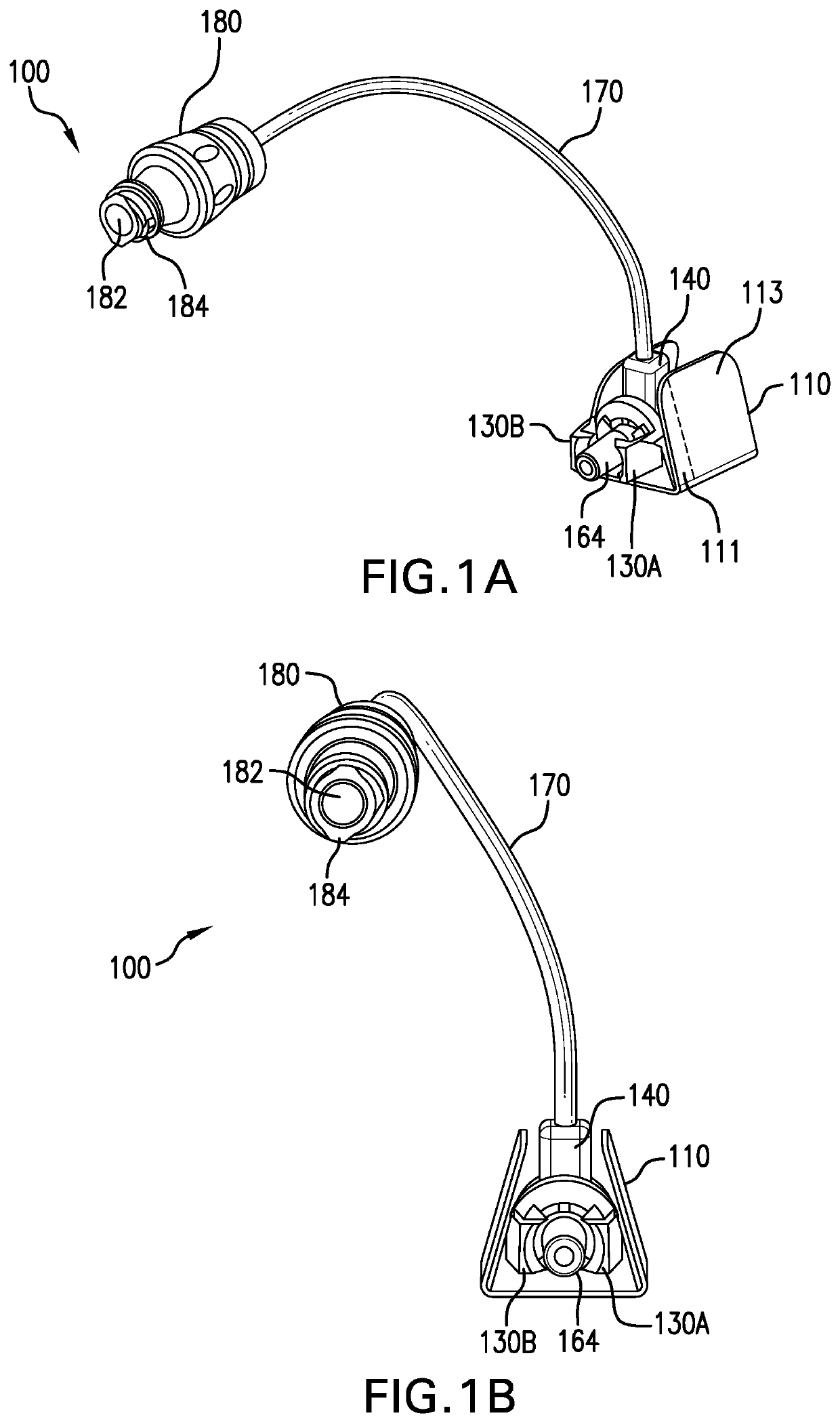
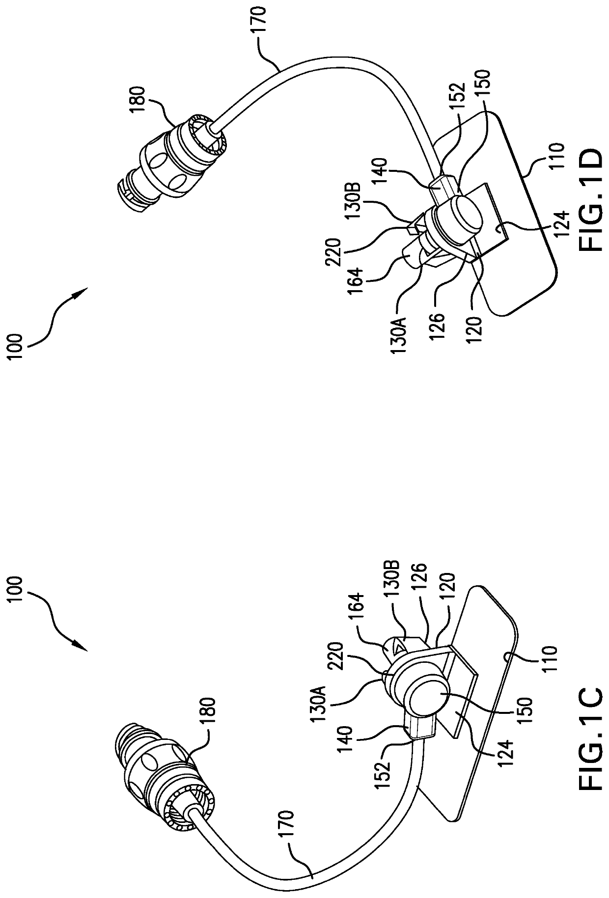
[0060]In illustrative embodiments, a vascular access site management system includes a stabilization body and a flow housing that is rotatable relative to the stabilization body. The flow housing may have a flow path extending through it to allow fluids to be introduced to or extracted from a patient via a catheter connected to the vascular access site management system. Additionally, in some embodiments, the vascular access site management system may include a needle free connector or other medical connector fluidly connected to the flow housing via a section of tubing. Details of illustrative embodiments are discussed below.

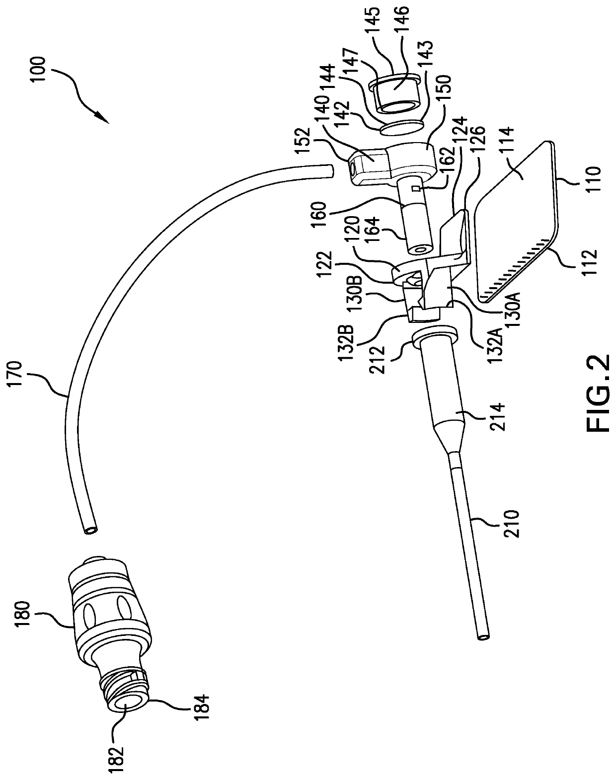
[0061]FIGS. 1A-1D schematically show a vascular access site management system 100 in both an undeployed state (FIGS. 1A and 1B) and a deployed state (FIGS. 1C and 1D), in accordance with some embodiments of the present invention. FIG. 2 shows an exploded view of the vascular access site management system 100. The management system 100 may include a stabilizatio...


PUM


Abstract

A vascular access site management system includes a stabilization body and a flow housing that is rotatable relative to the stabilization body. The flow housing may have a flow path extending through it to allow fluids to be introduced into or extracted from a patient via a catheter connected to the vascular access site management system. The vascular access site management system may also include a needle free connector fluidly connected to the flow housing via a section of tubing.

Description

PRIORITY[0001]This application claims priority from U.S. Provisional Application No. 62 / 641,649 filed Mar. 12, 2018, entitled “Vascular Access Site Management System,” and naming Todd Chelak, John Damarati, Nicholas Dennis and Nicholas Illsley as inventors, the disclosure of which is incorporated herein, in its entirety, by reference.RELATED UNITED STATES APPLICATIONS[0002]This patent application is related to co-pending U.S. patent application Ser. No. 16 / 298,175, entitled “Vascular Access Site Management System,” filed on even date herewith, and naming Todd Chelak, John Damarati, Nicholas Dennis and Nicholas Illsley as inventors, the disclosure of which is incorporated herein, in its entirety, by reference.TECHNICAL FIELD[0003]The present invention relates to vascular access sites, and more particularly to devices and systems that manage a vascular access site inclusive of an associated indwelling catheter such as a peripheral intravenous (IV) catheter.BACKGROUND ART[0004]In insta...

Claims


Application Information

Patent Timeline
Patent Type & Authority Patents(United States)
IPC IPC(8): A61M39/02A61M39/10A61M25/02A61M39/00
CPCA61M39/0247A61M25/02A61M39/10A61M2025/028A61M2039/0036A61M2039/027A61M2039/0258A61M2039/0261A61M2039/0273A61M2039/0282A61M39/1011A61M2005/1586
Inventor CHELAK, TODD M.DAMARATI, JOHNDENNIS, NICHOLASILLSLEY, NICHOLAS
Owner NP MEDICAL
Why Eureka
Try Eureka