
Manually detachable enclosure for replaceable filter elements and the like

a filter element and enclosure technology, applied in the field of detachable enclosures, can solve the problems of affecting the quality of the filter element, the process of changing the filter element is often more difficult and cumbersome, and the plastic filter wrench is often lost or broken, so as to achieve the effect of quick and easy attachment and removal

Active Publication Date: 2021-02-16
SUTTON JEPSON
View PDF1 Cites 3 Cited by
  • Summary
  • Abstract
  • Description
  • Claims
  • Application Information

AI Technical Summary

Benefits of technology

The present invention provides a detachable enclosure that can hold items that need to be periodically replaced, such as a filter. The enclosure can be easily attached and detached without tools, and it is secure and tight. Additionally, the enclosure can be mounted on a wall or used on a counter - it is flexible and can adapt to different surfaces.

Problems solved by technology

Consumers often complain about losing or breaking plastic filter wrenches, which are used only infrequently when changing a filter.
Even when over tightening does not occur during installation, pulse tightening frequently occurs over time.
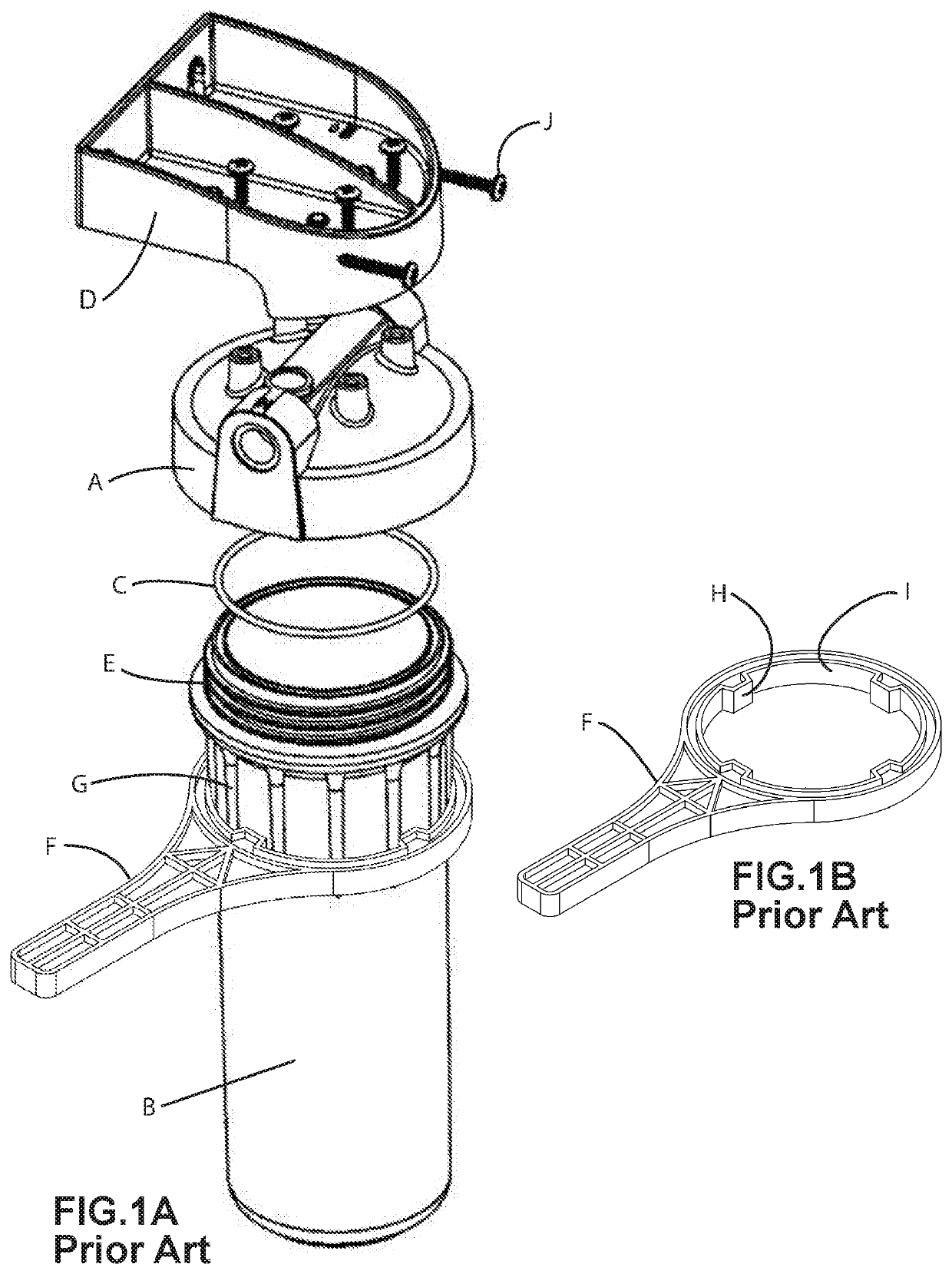
Wrenches of the type shown in FIG. 1B are employed for this purpose, making the process of changing a filter element more much more difficult and cumbersome.
The threaded connection (E) that characterizes most prior art commercial housings, has an additional disadvantage: when the connection is tightened there is circumferential displacement between the enclosure B and the lid A which subjects the o-ring seal C to significant shear forces from one side of the seal to the other, resulting in unpredictable cross sectional distortions and residual elastic energy in the seal itself.

Method used


Image

  • Manually detachable enclosure for replaceable filter elements and the like
  • Manually detachable enclosure for replaceable filter elements and the like
  • Manually detachable enclosure for replaceable filter elements and the like

Examples


Embodiment Construction

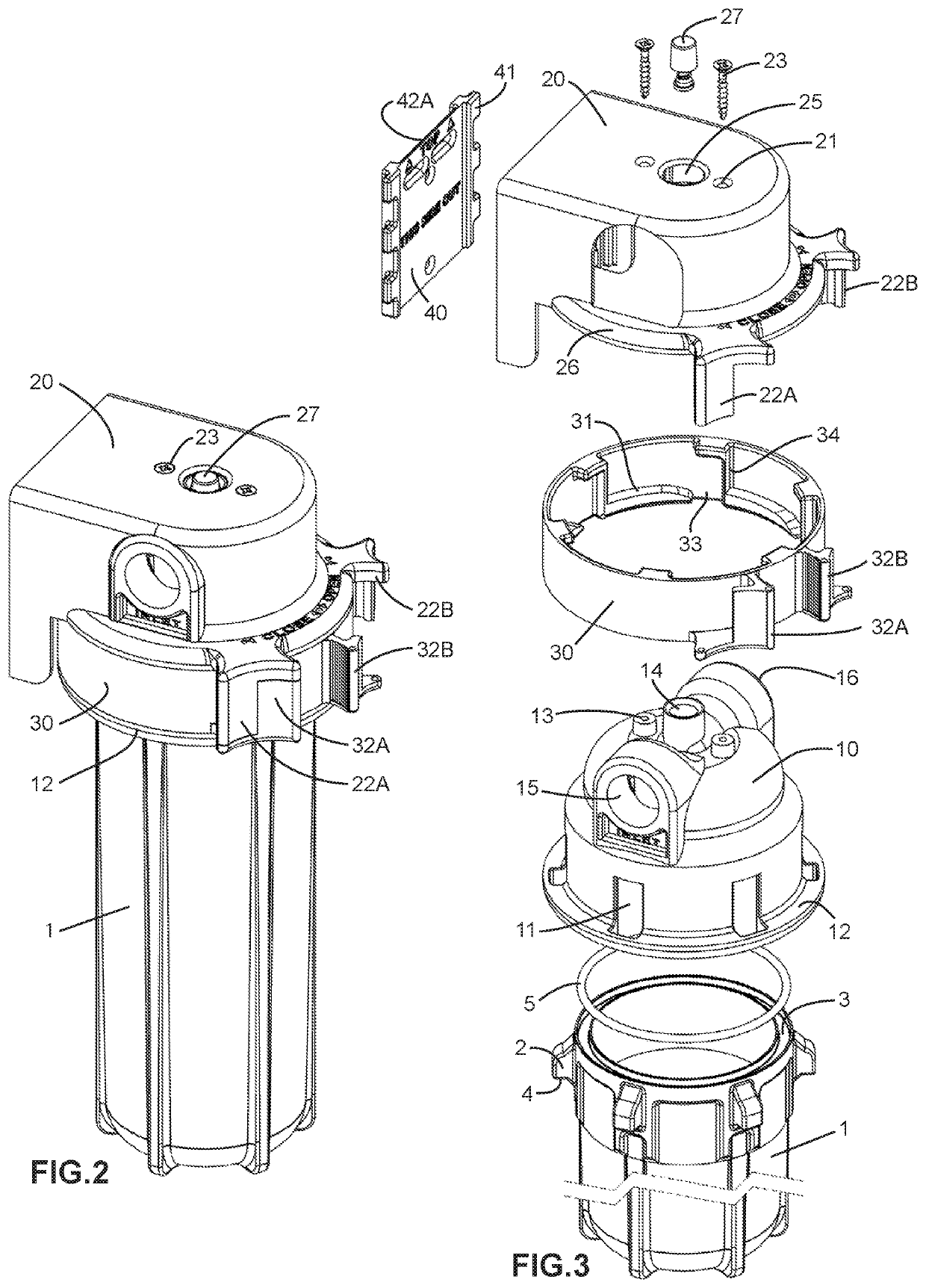
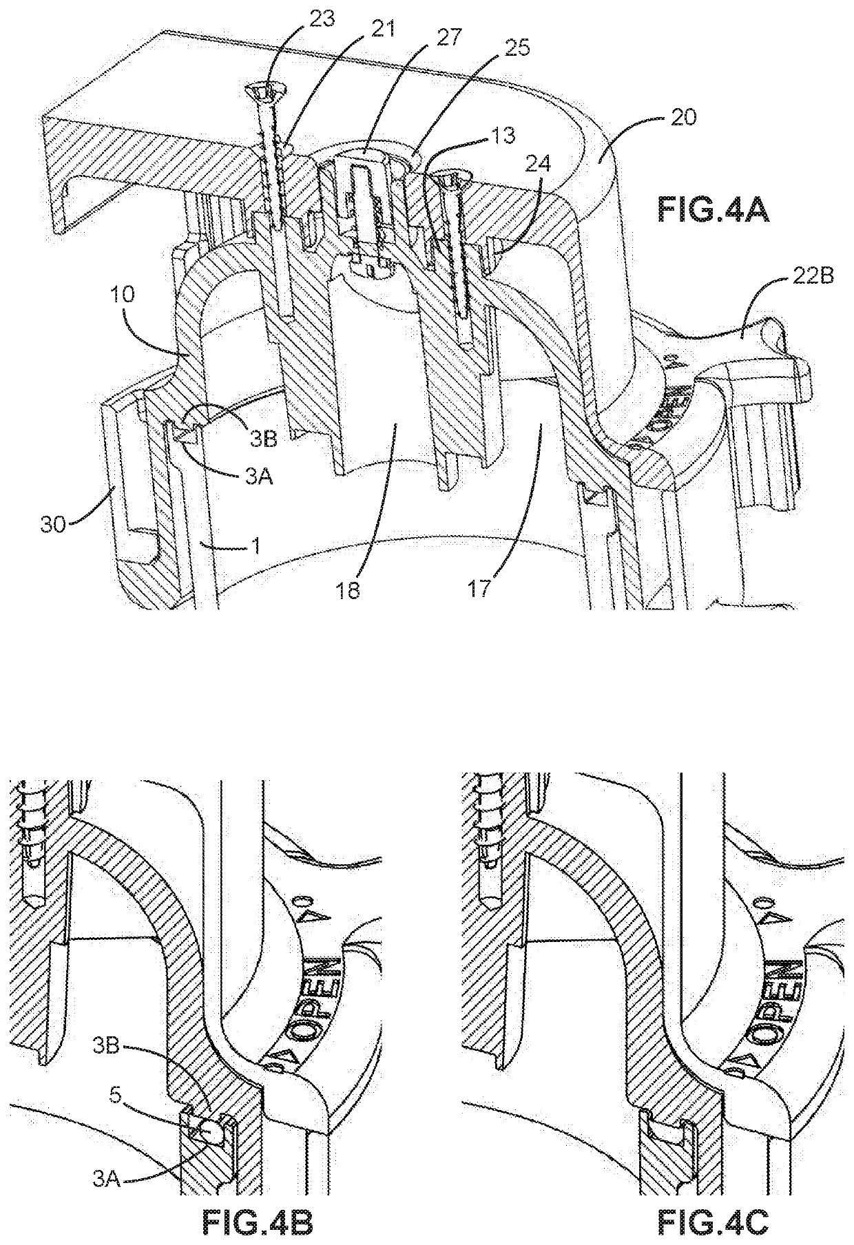
[0048]FIG. 2 is an assembled perspective view of one of the more useful and complex embodiments of the invention, namely a replaceable filter housing which is capable of being quickly opened and closed manually without the use of special tools and without the possibility of over tightening. FIG. 3 shows an exploded perspective view of the housing of FIG. 2, without an enclosed replaceable filter. FIG. 8 shows a sectional view of the FIG. 2 housing with an enclosed filter element 50. The housing shown in FIGS. 2 and 3 includes the following basic components:

[0049]An enclosure 1, which includes six radial pins 2 extending from the open end of the enclosure 1. The enclosure 1 also includes a recessed seat3A designed to receive a seal 5.

[0050]A closure or lid 10 (best shown in FIG. 3) includes six slots 11 which are configured to receive the six corresponding pins 2 when the lid 10 is engaged over the open end of the enclosure 1. The lid 10 also includes a load bearing circumferential f...


PUM

PropertyMeasurementUnit
Massaaaaaaaaaa
Massaaaaaaaaaa
Forceaaaaaaaaaa

Abstract

An apparatus and method for using a detachable sealed enclosure for containing and quickly accessing filter elements and the like without the use of tools and without the possibility of initial or subsequent over tightening. A first set of paired protrusions receive lateral pinch forces which draw the enclosure into a sealed connection with a lid while selectively compressing a seal between these components. A second set of paired protrusions receive lateral pinch forces which release the sealed connection, providing access to the enclosure content.

Description

I. BACKGROUNDA. RELATED APPLICATION[0001]This application is related to co-pending application entitled “Quick Change Filter Housing” that was filed Jun. 3, 2017 and assigned Ser. No. 29 / 606,366 (now U.S. Pat. No. D832,394, issued Oct. 30, 2018). The disclosure in application Ser. No. 29 / 606,366 as filed on Jun. 3, 2017 is incorporated herein by reference.B. FIELD OF INVENTION[0002]The invention described in the present application relates to a detachable enclosure that in one preferred embodiment is used to contain and support a replaceable filter within a directed flow of water to be filtered prior to use; more particularly, the present invention relates to a container having manually detachable sections that allow for the quick removal and replacement of an enclosed filter element without the use of tools.C. PRIOR ART FILTER CONTAINERS AND ASSEMBLY / DISASSEMBLY MECHANISMS[0003]There are tens of thousands of patents describing various forms of enclosures, containers and housings ad...

Claims


Application Information

Patent Timeline
IPC IPC(8): B01D35/30
CPCB01D35/30B01D2201/302B01D2201/304B01D2201/305B01D2201/306B01D2201/307B01D29/21B01D29/96B01D35/303B01D2201/24B01D2201/342B01D2201/4015B01D2201/4023
Inventor SUTTON, JEPSON
Owner SUTTON JEPSON
Learn More