Device and method for forecasting wear in brake linings

a technology for brake linings and forecasting devices, applied in brake systems, braking components, transportation and packaging, etc., can solve problems such as reducing lining thickness continuously, exposing brake linings of friction braking systems, and braking systems, and achieve the effect of reducing the number of sensors

Active Publication Date: 2021-02-16
SIEMENS MOBILITY AUSTRIA GMBH
View PDF15 Cites 1 Cited by
  • Summary
  • Abstract
  • Description
  • Claims
  • Application Information

AI Technical Summary

Benefits of technology

[0008]It is an object of the present invention is to provide a device and method for reducing the number of sensors that are required to forecast wear in the context of brake linings.
[0009]This and other objects and advantages are achieved in accordance with the invention by a device and method that has a low level of technical complexity and is therefore highly resilient. The device and method moreover are economical to realize, because expensive sensors are omitted.
[0010]As a result of using field data to parameterize the model, a wear forecast that is highly realistic and very accurate is ensured.
[0013]The forecast calculation is also possible in relation to diagonal wear. It is therefore possible both to detect that limit values for diagonal wear have been reached and to provide information relating to improvements in the friction braking system (e.g., optimization of the pressure point between lining and disc) to reduce diagonal wear.

Problems solved by technology

Brake linings of friction braking systems are exposed to wear during use, whereby the lining thickness is continuously reduced.
If a brake lining falls below its specified minimum thickness, it must be replaced, because otherwise damage to the braking system may occur or the braking effect may be diminished.
The identification of the allowable limit level requires continuous monitoring of the lining thickness using methods that are expensive technically, in terms of time, and financially.

Method used


Image

  • Device and method for forecasting wear in brake linings
  • Device and method for forecasting wear in brake linings
  • Device and method for forecasting wear in brake linings

Examples


Embodiment Construction

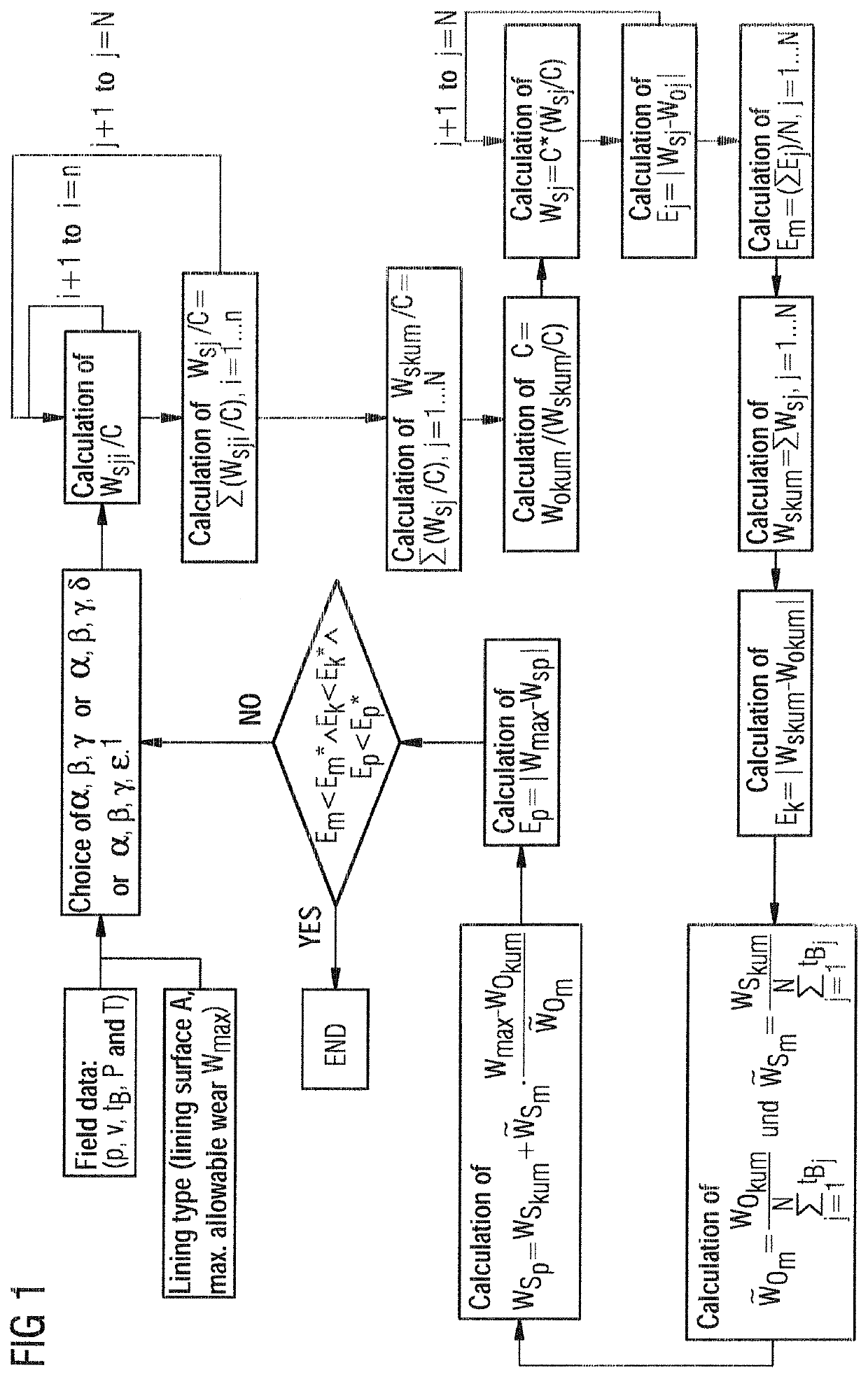
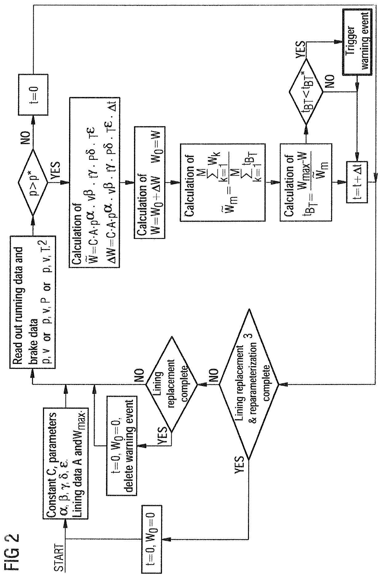
[0019]In accordance with the invention, the abrasion of brake linings of rail vehicles is determined via a method in which a wear rate {tilde over (W)} is determined in accordance with the following relationship:

{tilde over (W)}=C·A·pα·vβ·tBγ·Pδ·Tε  Eq. 1

where

C=general constant,

A=lining surface,

p=contact pressure,

v=sliding speed,

tB=braking time,

P=brake power,

T=contact temperature of the friction pairing,

α=material parameter pressure,

β=material parameter speed,

γ=material parameter braking time,

δ=material parameter brake power, and

ε=material parameter temperature.

[0020]Significant factors for determining the wear rate {tilde over (W)} are lining surface A, contact pressure p, sliding speed v and braking time tB. The use of the contact temperature T and the brake power P is optional, i.e., not essential.

[0021]While the lining surface A is derived from the structural features of the brake, the contact pressure p, the sliding speed v and the braking time tB are determined continuously du...


PUM


Abstract

A device and method for forecasting the brake lining wear, in particular the brake lining of rail vehicles, wherein the lining thicknesses, the sliding speed, the contact pressure, the total braking time, as well as optionally the temperature or the brake power are determined in a parameterization process during test drives with measurements at predefined time intervals, and the wear, the constant, as well as the material parameters are determined therefrom, where during the operating state, the wear rates are determined via the now known values of the material parameters and of the constants, and the wear is determined therefrom and, from the maximum allowable wear values, a remaining total braking time is then determined until the next lining replacement is required.

Description

CROSS-REFERENCE TO RELATED APPLICATIONS[0001]This is a U.S. national stage of application No. PCT / EP2015 / 075679 filed 4 Nov. 2015, and claims the priority of Australian application No. A50064 / 2015 filed Jan. 29, 2015, the content of which is incorporated herein by reference in its entirety.BACKGROUND OF THE INVENTION1. Field of the Invention[0002]The invention relates to a device and method for forecasting the wear in brake linings, of rail vehicles in particular.2. Description of the Related Art[0003]Brake linings of friction braking systems are exposed to wear during use, whereby the lining thickness is continuously reduced. If a brake lining falls below its specified minimum thickness, it must be replaced, because otherwise damage to the braking system may occur or the braking effect may be diminished.[0004]The identification of the allowable limit level requires continuous monitoring of the lining thickness using methods that are expensive technically, in terms of time, and fina...

Claims


Application Information

Patent Timeline
Patent Type & Authority Patents(United States)
IPC IPC(8): B60T17/22B61H5/00F16D66/02F16D66/00
CPCB60T17/228B60T17/221B61H5/00F16D66/02F16D66/027F16D2066/006B60T17/22A01C7/102A01C7/122A01C19/02
Inventor PREHOFER, BORIS ANDRE
Owner SIEMENS MOBILITY AUSTRIA GMBH
Why Eureka
Try Eureka