No blade bit

a drill bit and blade technology, applied in the field of drill bits, can solve the problems of excessive wear or other damage to one or more cutting elements and/or blades, high and irregular torque responses, and several problems of the drill bit, so as to reduce the amount of torque experienced, reduce the occurrence of bit whirl and excessive damage, and maintain the effect of torque profil

Active Publication Date: 2021-02-16
ULTERRA DRILLING TECH LP
View PDF9 Cites 0 Cited by
  • Summary
  • Abstract
  • Description
  • Claims
  • Application Information

AI Technical Summary

Benefits of technology

[0002]Embodiments of the present invention are directed to PDC drill bits that have an asymmetrical arrangement of cutters on a drilling face of the bit. Each of the cutters has a unique angular position relative to a central axis of the bit. In some embodiments, each cutter (or a substantial number of the cutters) may have a unique radial position as well. The asymmetrical arrangement of cutters at unique angular and / or radial positions in a bladeless design reduces the concentration of cutters at similar angles and thus helps reduce the amount of torque experienced at any individual cutter or subset of cutters. This results in a PDC drill bit that exhibits a more consistent torque profile and reduces the occurrence of bit whirl and excessive damage to the cutters themselves. PDC drill bits according to the present invention also include number of knots that project outward from the drilling face and that serve as mounting sites for the various cutters. These knots provide mounting sites for the cutters that may project outward from the head of the PDC drill bit at different distances and / or angles such that the cutters define a desired cutting profile of the PDC drill bit. The drill bits described herein also provide fluid ports that are arranged to sit between multiple ones of the knots and deliver cooling fluid to all or a substantial portion of a surface of each cutter. As a substantial surface area of each cutter is in contact with the cooling fluid, the cutters are cooled much more effectively than in conventional PDC bits that only supply cooling fluid to the cutting edge of each cutting element.

Problems solved by technology

Due to the arrangement of the blades and cutting elements, these bits suffer from several problems.
Notably, the concentrations of cutters on each blade (at a same or similar angular position) cause high and irregular torque responses.
The high and irregular torque responses may lead to bit whirling, as well as result in especially high forces being applied to a small subset of the cutting elements on a particular blade that may cause excessive wear or other damage to one or more of the cutting elements and / or blades.
However, such positioning only allows these ports to supply cooling fluid to the cutting edge of the cutting element, which provides sub-optimum cooling ability.

Method used


Image

  • No blade bit
  • No blade bit
  • No blade bit

Examples


Embodiment Construction

[0021]The subject matter of embodiments of the present invention is described here with specificity to meet statutory requirements, but this description is not necessarily intended to limit the scope of the claims. The claimed subject matter may be embodied in other ways, may include different elements or steps, and may be used in conjunction with other existing or future technologies. This description should not be interpreted as implying any particular order or arrangement among or between various steps or elements except when the order of individual steps or arrangement of elements is explicitly described.

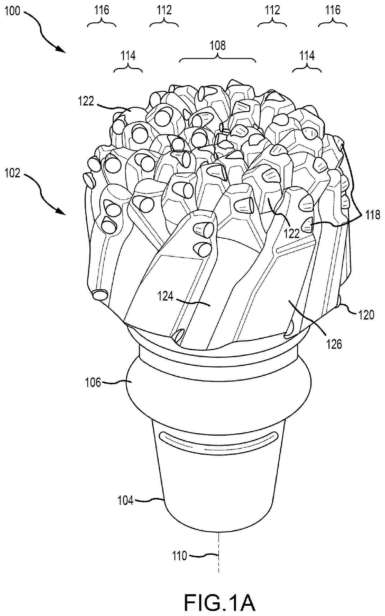
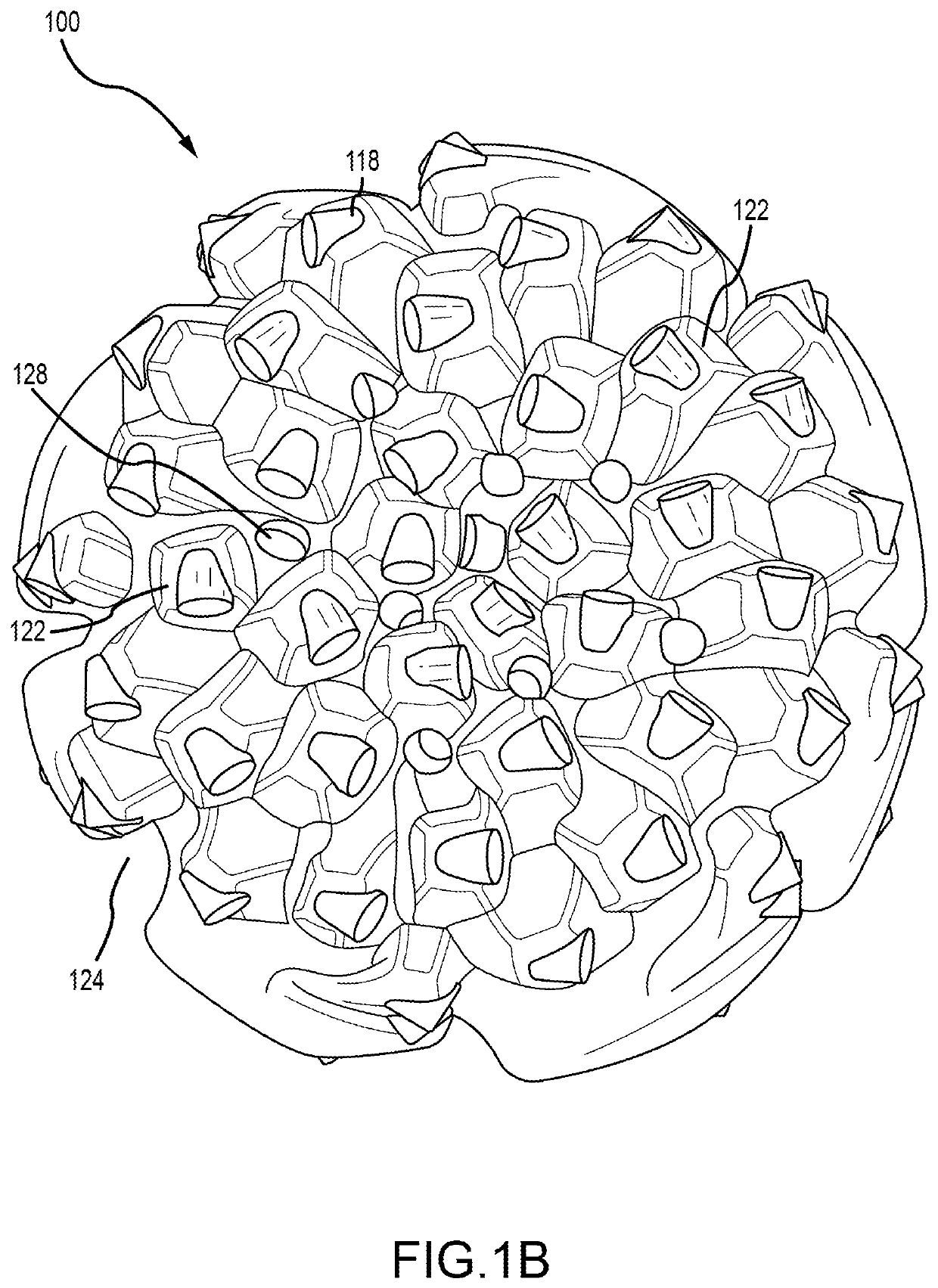
[0022]Embodiments of the present invention are directed to improved polycrystalline diamond compact (PDC) drill bits that generate reduced and more consistent torque profiles, as well as that reduce the amount of bit whirl experienced as compared to conventional PDC drill bits. During bit whirl, the instantaneous center of rotation moves around the face of the bit, and the bit w...


PUM


Abstract

A bladeless polycrystalline diamond compact (PDC) drill bit includes a head having a plurality of knots protruding from a drilling face of the head. Each of the plurality of knots includes a single cutter. Each of the cutters is arranged about a central axis of the head such that each cutter has a unique radial position and angular position relative to the central axis. The head defines at least one fluid port extending through the drilling surface.

Description

BACKGROUND OF THE INVENTION[0001]Conventional PDC drill bits include a number of blades arranged about a drilling face of the bit, with each blade supporting a number of cutting elements. Due to the arrangement of the blades and cutting elements, these bits suffer from several problems. Notably, the concentrations of cutters on each blade (at a same or similar angular position) cause high and irregular torque responses. This is especially true for cutters positioned near an outer periphery of the bit, since the torque generated on any cutter and / or blade is a function of the radial distance of the cutter from the center of the bit, with most outward cutters generating greater torque values. The high and irregular torque responses may lead to bit whirling, as well as result in especially high forces being applied to a small subset of the cutting elements on a particular blade that may cause excessive wear or other damage to one or more of the cutting elements and / or blades. Additiona...

Claims


Application Information

Patent Timeline
Patent Type & Authority Patents(United States)
IPC IPC(8): E21B10/43E21B10/567E21B10/60
CPCE21B10/43E21B10/602E21B10/567
Inventor ROTHE, MITCHELLCHREST, BEN
Owner ULTERRA DRILLING TECH LP
Why Eureka
Try Eureka