Eureka AIR delivers breakthrough ideas for toughest innovation challenges, trusted by R&D personnel around the world.

Filter device with coupling element

Active Publication Date: 2021-02-23
HYDAC FILTERTECHNIK GMBH
View PDF10 Cites 0 Cited by
  • Summary
  • Abstract
  • Description
  • Claims
  • Application Information

AI Technical Summary

Benefits of technology

The invention introduces a new filter device that is easier to maintain. This is accomplished by incorporating a coupling device that allows for rotating one screw connection to tighten another screw connection. This enables both parts to be tightened simultaneously, reducing the time required for maintenance.

Problems solved by technology

Even though the mentioned, known filter device is characterized by a favorable operating behavior insofar as the filter element is securely fixed in the filter housing by a screw connection, the maintenance is relatively time consuming, because for assembly and disassembly of the filter elements in question.

Method used


Image

  • Filter device with coupling element
  • Filter device with coupling element
  • Filter device with coupling element

Examples


Embodiment Construction

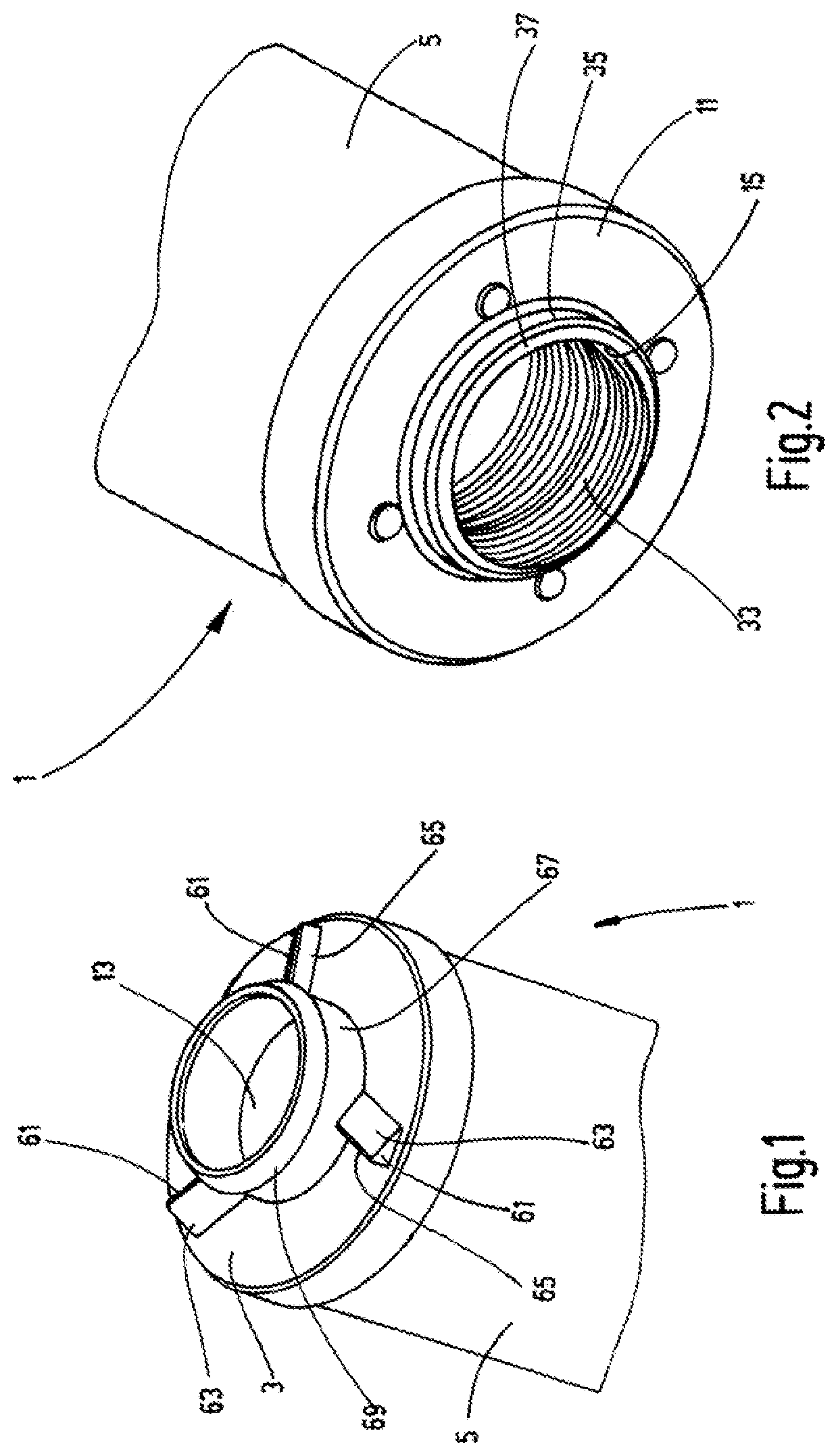
[0028]FIG. 1 shows only the upper end portion of a filter element 1, which is provided for use in the exemplary embodiment of the filter device according to the invention shown in the drawings. The filter element 1 formed in the manner of a replaceable filter cartridge has at its upper end, as shown in FIG. 1, an end cap 3. End cap 3 forms a border for the facing end of a filter medium 5 in the manner typical for such filter elements. The filter element preferably has several pleated layers and forms a hollow cylinder, which, cf. FIGS. 4 and 5, surrounds an inner filter cavity 7, in which a fluid-permeable support tube 9 is located. The support tube end facing the end cap 3 has been mounted in conjunction with the end of the filter medium 5 in the end cap 3. An end cap 11 is located at the lower end shown in FIG. 2, which lower end cap forms the enclosure for the facing end of the filter medium 5 and the support tube 9 in the same manner as the upper end cap 3. Unlike the upper end ...


PUM

PropertyMeasurementUnit
Angleaaaaaaaaaa
Rotational stateaaaaaaaaaa
Energyaaaaaaaaaa

Abstract

A filter device has a filter element (1) received in a filter housing of at least two interconnectable housing parts (17, 19). The filter element (1) can be fixed to a housing part (19) in a removable manner by one screw connection (32, 33). An additional screw connection (17, 41) is provided for connecting the housing parts (17, 19). To transmit a torque between threaded elements (33) of the one screw connection (32, 33) and of the additional screw connection (41), the threaded elements are rotatable relative to each other. A coupling device (43, 46, 61) is added that allows an additional rotational movement of the threaded element (17) of the additional screw connection (41) when the threaded element (33) of the one screw connection (32, 33) reaches the fixed rotational state.

Description

FIELD OF THE INVENTION[0001]The invention relates to a filter device having a filter element, which can be mounted in a filter housing. The filter housing has at least two interconnected housing parts. The filter element can be detachably attached to a housing part by a first screw connection. A second screw connection is provided for connecting the housing parts.BACKGROUND OF THE INVENTION[0002]Filter devices having at least one filter element, which can be mounted in a housing, through which at a certain system pressure or fluid operating pressure fluids can flow are state of the art and are widely used, for instance, in system branches of hydraulic systems through which hydraulic oil flows. A filter device of the type mentioned, in which the filter element can be connected to a housing part by a screw connection and in which the housing parts forming the housing of the device can also be connected to one another by a screw connection, is disclosed in the document DE 10 2011 120 6...

Claims


Application Information

Patent Timeline
IPC IPC(8): B01D27/08B01D29/96B01D35/30B01D29/21B01D35/14B01D35/00
CPCB01D29/96B01D27/08B01D29/21B01D35/14B01D35/30B01D35/306B01D35/005B01D2201/291B01D2201/295B01D2201/301B01D2201/302B01D2201/305B01D2201/306B01D2201/40B01D2201/4007B01D2201/4023B01D2201/4061B01D2201/4076B01D2201/4084B01D2201/4092B01D2265/025
Inventor MAURER, PATRICKHENNES, STEFANSAKRASCHINSKY, MICHAEL
Owner HYDAC FILTERTECHNIK GMBH
Why Eureka
Eureka Blog
Learn More