On-board centralized system for regulating the pressure of the tyres of a motor-vehicle

a centralized system and tyre pressure technology, applied in the field of motor vehicles, can solve the problems of inaccurate estimation based on the difference between the speed, general accuracy is not good, and even fallsacious, so as to achieve accurate control of the pressure of the tyres through simple, safe and reliable means.

Active Publication Date: 2021-02-23
CENT RICERCHE FIAT SCPA
View PDF11 Cites 0 Cited by
  • Summary
  • Abstract
  • Description
  • Claims
  • Application Information

AI Technical Summary

Benefits of technology

[0016]The object of the present invention is to provide an on-board centralized system for regulating the pressure of the tyres of a motor-vehicle that will be sturdy, safe, and reliable, and that in particular will guarantee maintenance of a minimum safety level of the pressure in the inner chambers of the tyres of the motor-vehicle, also in the case of breakdown of the air-supply circuit, moreover enabling isolation of the tyre from the remaining parts of the air-supply circuit when the system is in the resting condition.
[0020]Thanks to the above characteristics, the system is able to guarantee always, in any operating condition, and also in the case of breakdown of the air-supply circuit, a minimum level of the pressure in the tyres of the motor-vehicle for safety reasons. By means of the configuration described there is moreover obtained the advantage of maintaining the environment downstream of the inflation and deflation valves—set in the proximity of the access to the space comprised between the tyres and the rim—normally disconnected from the parts of the air-supply circuit set upstream of the aforesaid valves, enabling depressurization of the pneumatic rotary joint during the resting steps of the system and enabling an isolation of the tyre in the case of failure of parts of the system set upstream of the inflation and deflation valves.
[0024]Once again in the aforesaid preferred embodiment, the plenum of the wheel is a cavity formed in the front surface of the wheel and closed by a cover removably fastened to the wheel. The aforesaid plenum is in communication with the air-supply circuit by means of a tubular connection element (having a first end connected to the respective wheel spindle and a second end received through a hole formed in a front wall of the wheel that constitutes the bottom of the aforesaid cavity defining the plenum). The tubular element is received through the hole with interposition of a tubular supporting sealing member. This configuration enables the operations of installation and removal of the wheel to remain unaltered as compared to conventional solutions.
[0026]Thanks to the aforesaid characteristics, the system according to the invention is able to ensure, with extremely simple, safe, and reliable means, accurate control of the pressure of the tyres and / or a variation upwards or downwards of the pressure, according to the various operating characteristics of the vehicle itself, for example according to the load of the motor-vehicle and / or the type of terrain.

Problems solved by technology

Indirect TPM systems, in fact, provide an estimate based upon the difference between the speed of rotation of the different wheels and are generally far from precise and even fallacious in the case where all the tyres are deflated in the same way.
Direct TPM systems, on the other hand, require installation of pressure sensors directly within the inner chamber of the tyres in wireless communication with the control unit, with all the complications that this entails.

Method used


Image

  • On-board centralized system for regulating the pressure of the tyres of a motor-vehicle
  • On-board centralized system for regulating the pressure of the tyres of a motor-vehicle
  • On-board centralized system for regulating the pressure of the tyres of a motor-vehicle

Examples


Embodiment Construction

[0027]Further characteristics and advantages of the invention will emerge from the ensuing description, with reference to the annexed drawings, which are provided purely by way of non-limiting example and in which:

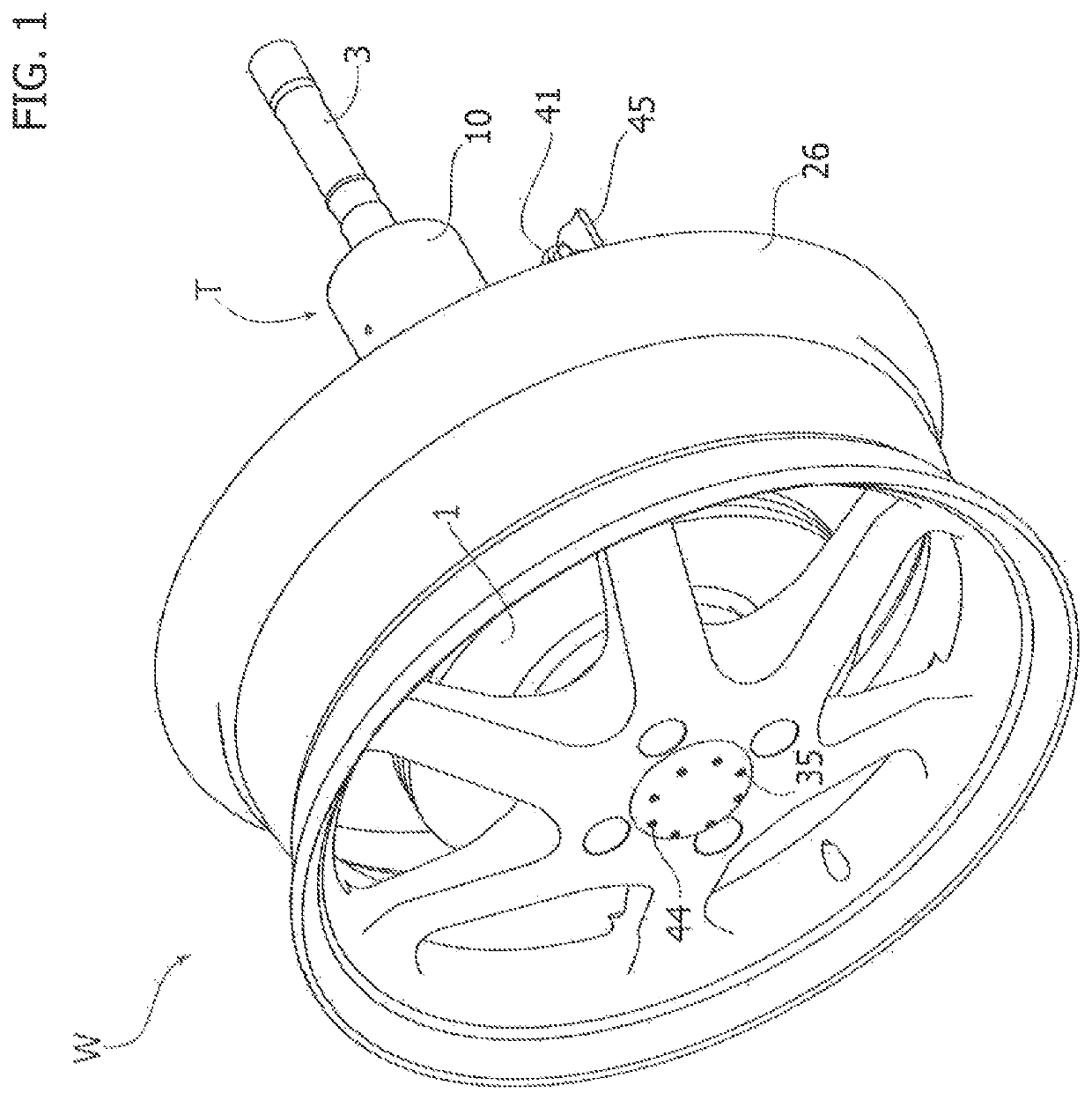
[0028]FIG. 1 is a perspective view of a driving wheel of a motor-vehicle with the system installed;

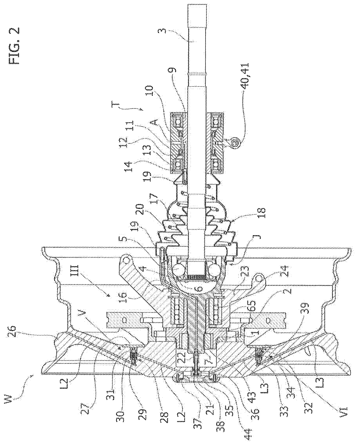
[0029]FIG. 2 is a cross-sectional view of the part of the system associated to the driving wheel, according to a preferred embodiment of the invention;

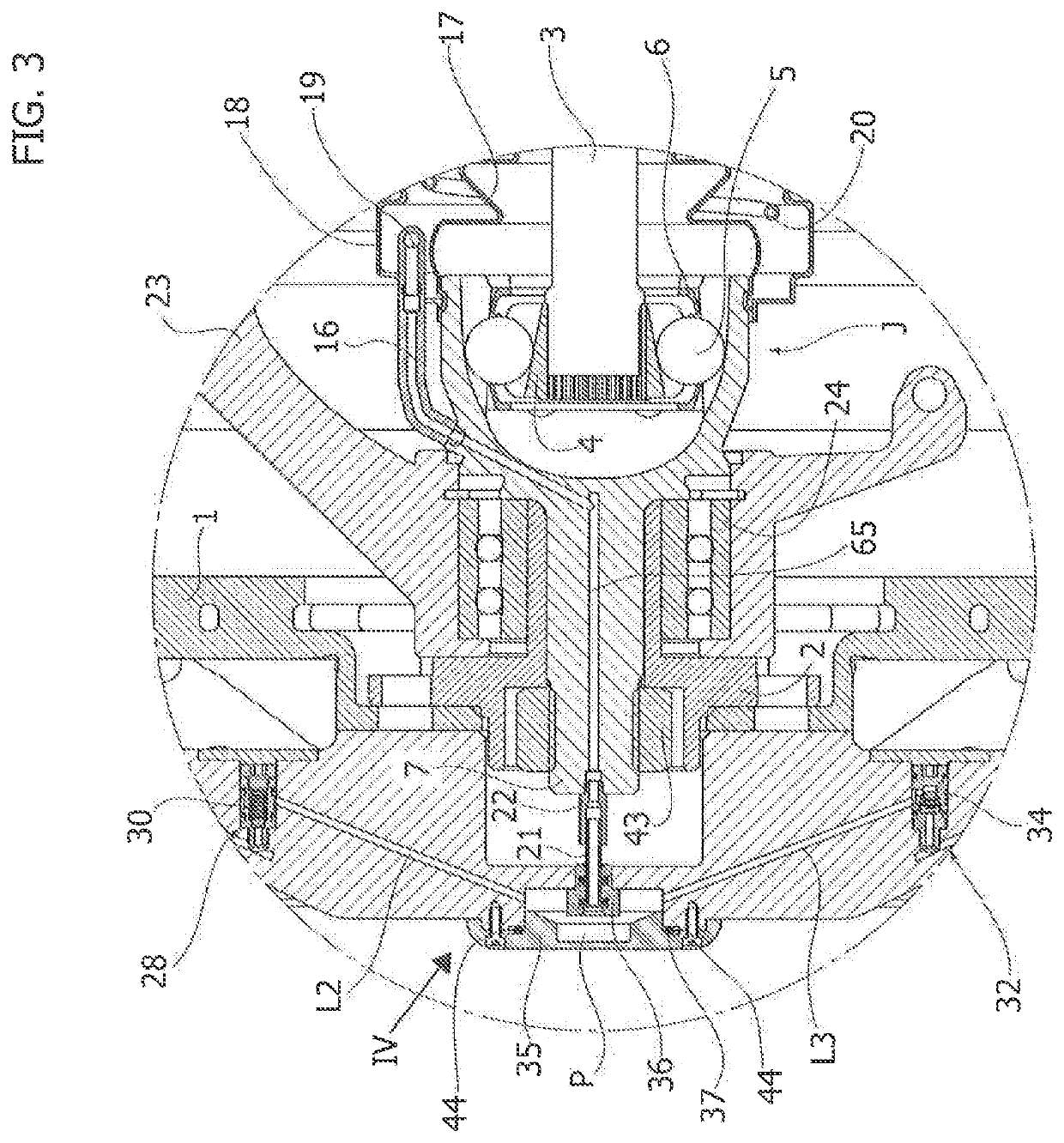
[0030]FIG. 3 is a view, at an enlarged scale, of the details denoted by the reference III in FIG. 2;

[0031]FIG. 4 is a view, at an enlarged scale, of the details denoted by the reference IV in FIG. 3;

[0032]FIGS. 5 and 6 are views, at an enlarged scale, of the details denoted by the references V and VI in FIG. 2;

[0033]FIGS. 7 and 8 are perspective views of some parts of the system illustrated in FIG. 2;

[0034]FIG. 9 is a front view of the details illustrated in FIG. 1;

[0035]FIG. 10 is a perspective view of a driving wheel of a mot...


PUM


Abstract

An on-board centralized system for regulating pressure of tyres of a vehicle includes a pressurized air source, a circuit communicating the source with a plenum of each wheel, and an arrangement for connecting the plenum of each wheel to the inner chamber of the respective tyre that includes first and second connection lines for deflation and inflation, respectively, of the tyre, and first and second one-way valves interposed, respectively, in the first and second connection lines to allow only a flow of air respectively from and to the inner chamber. The first valve includes a spring having a pre-set load so as to isolate the inner chamber from a part of the circuit upstream of the first valve when said upstream part is at atmospheric pressure, and to guarantee a pre-set minimum value of pressure in the inner chamber when the upstream part is at a pressure lower than atmospheric pressure.

Description

CROSS-REFERENCE TO RELATED APPLICATIONS[0001]This application is a 371 U.S. National Stage of International Application No. PCT / IB2016 / 056609, filed Nov. 3, 2016, which claims priority to Italian Application No. 102015000076131, filed on Nov. 24, 2015. The disclosure of each of the above applications is incorporated herein by reference in their entirety.FIELD OF THE INVENTION[0002]The present invention relates in general to motor-vehicles and in particular to an on-board centralized system for regulating the pressure of the tyres of a motor-vehicle of the type referred to in the preamble of the annexed claim 1.[0003]The invention may be used to particular advantage in passenger cars and light commercial vehicles.[0004]Centralized automatic systems for regulating the inflation pressure of the tyres of a motor-vehicle (the so-called Central Tyre-Inflation Systems—CTISs) have been known for some time. They are able to manage autonomously the pressure of tyres of a motor-vehicle through...

Claims


Application Information

Patent Timeline
Patent Type & Authority Patents(United States)
IPC IPC(8): B60C23/00
CPCB60C23/00327B60C23/00318B60C23/00354B60C23/00363B60C23/003B60C23/00372B60C23/00336
Inventor VITOLO, ROBERTOD'AMBROSIO, STEFANOSALAMONE, NICOLOMARTORANA, GIUSEPPEIELUZZI, MICHELEGABIATI, GIOVANNI LUIGISCANTAMBURLO, DARIO
Owner CENT RICERCHE FIAT SCPA
Why Eureka
Try Eureka