Filter panel with structures support grid and drum filter with said filter panel

a filter panel and structure technology, applied in the field of filter panels, can solve the problems of reducing the flow capacity, requiring the replacement of entire cloth, and not solving the flow problem in a satisfactory manner

Active Publication Date: 2021-03-16
VEOLIA WATER SOLUTIONS & TECH SUPPORT
View PDF99 Cites 2 Cited by
  • Summary
  • Abstract
  • Description
  • Claims
  • Application Information

AI Technical Summary

Benefits of technology

[0007]According to a first aspect, these and other objects, and / or advantages that will be apparent from the following description of embodiments, are achieved, in full or at least in part, by a filter panel for a drum filter which is used for filtering off solid particles from a liquid. The filter panel comprises a first side being adapted to be attached to a drum of said drum filter, a second side being adapted to receive a filter cloth, and a plurality of through holes extending from said first side to said second side, each hole defining one or more side walls. The filter panel is characterized in that at least one of said holes comprises an inclined side wall. By inclining the side walls of the holes, the liquid lift of the filter panel may be controlled and adapted for the specific drum filter to which it has been attached. To solve the problem stated above, the side walls may be inclined in a manner so that the liquid lift of the filter panel is reduced. In turn, the amount of unfiltered liquid escaping from the drum via the collecting channel will be heavily reduced. In some other drum filters, it may be desirable to increase the liquid lift, which easily is achieved by simply turning the filter panels on the drum filter over. This could, for example, be desirable when filtering large particles from the liquid which are intended to get stuck on the side wall of the holes of the filter panel and follow the same up and into the collecting channel. In turn, the collecting channel could potentially be placed at a higher level within the drum so that the active filtering area of the same may be increased.

Problems solved by technology

A big problem in the context is the reduced flow capacity resulting from surface tensions present in the liquid phase and generated on the underside of the filter cloth.
However, this measure does not solve the flow problem in a satisfactory manner.
Another serious disadvantage of known filter systems is that the entire cloth must be replaced in case it is damaged, which is a complicated, time-wasting and expensive operation because the cloth is usually mounted in a frame.
There are, however, problems associated with the solution described above.
This decreases the effect of the filtration by carrying unnecessarily unfiltrated liquid outside of the drum with the solid particles removed.

Method used


Image

  • Filter panel with structures support grid and drum filter with said filter panel
  • Filter panel with structures support grid and drum filter with said filter panel
  • Filter panel with structures support grid and drum filter with said filter panel

Examples


Embodiment Construction

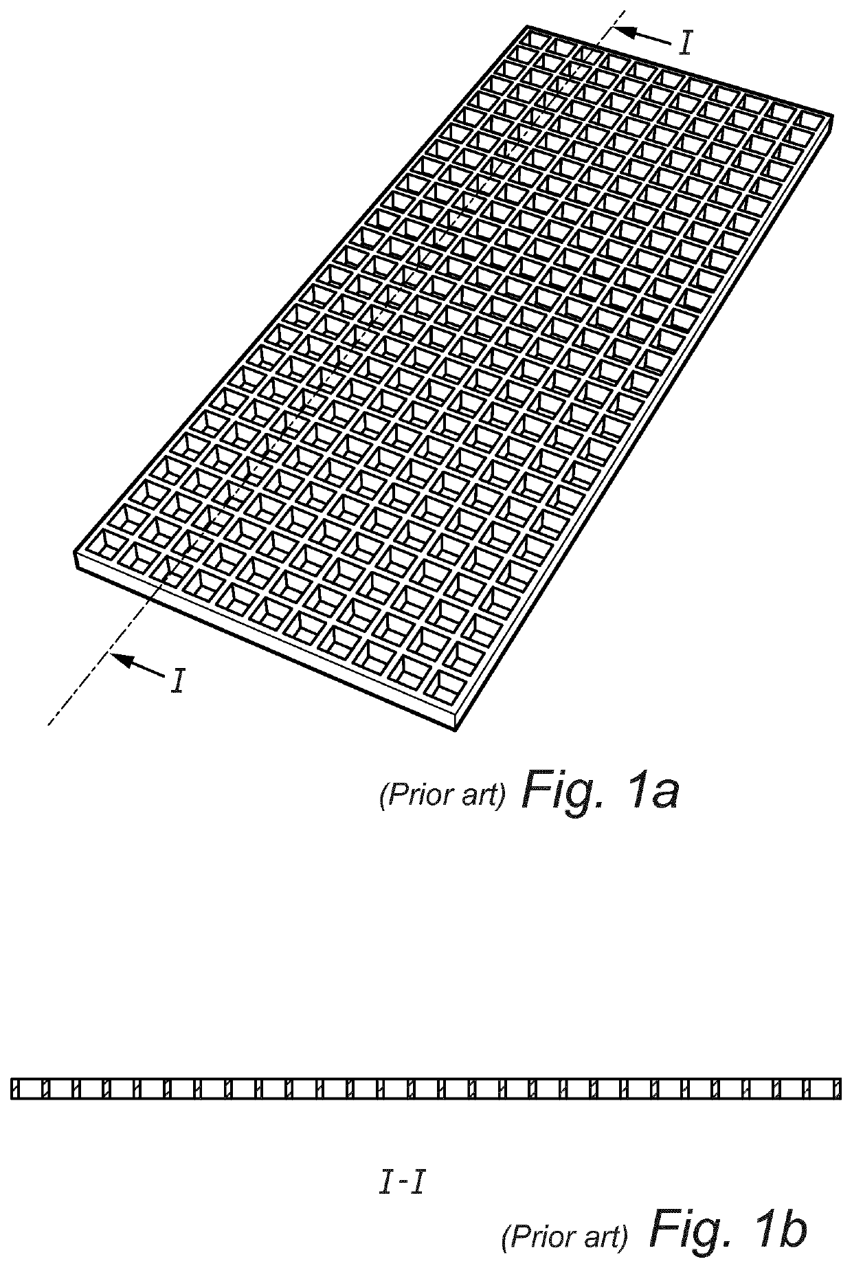
[0022]In FIG. 1a and FIG. 1b, a conventional filter panel according to prior art is illustrated. The filter panel is adapted to be used in connection with a drum filter for filtering off solid particles from a liquid.

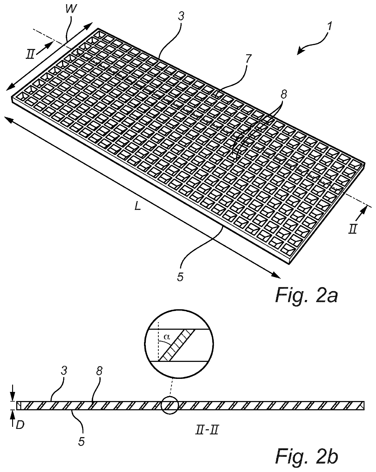
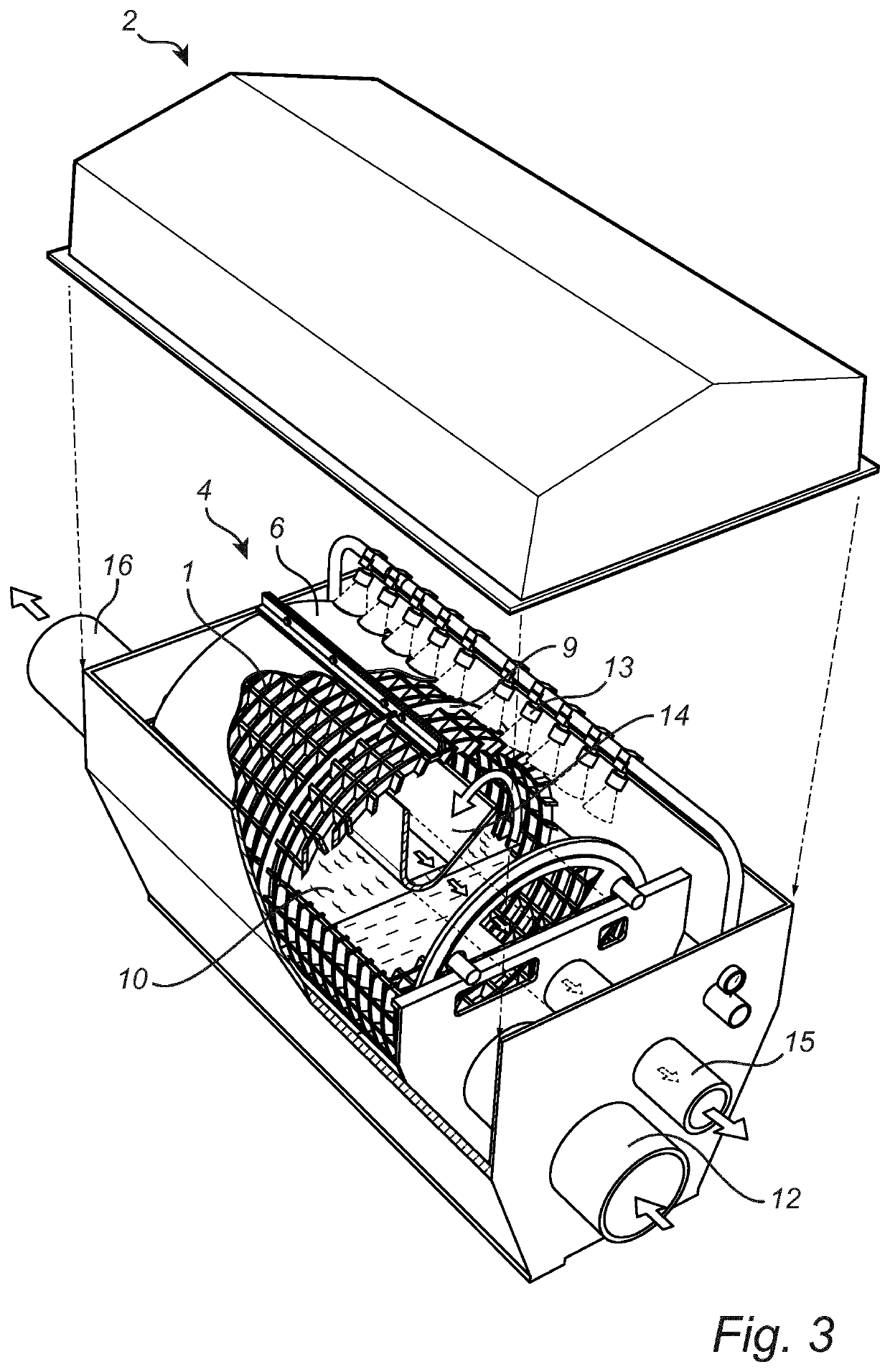
[0023]FIG. 2a and FIG. 2b illustrates a filter panel 1 according to one exemplary embodiment of the present invention. The filter panel 1 is to be used in connection with a drum filter 2 for filtering off solid particles from a liquid. The filter panel 1 comprises a first side 3 which is adapted to be attached to a drum 4 of said drum filter 2, and a second side 5 which is adapted to receive a filter cloth 6. The filter panel 1 extends in a length direction L, a width direction W, and a depth direction D. The filter panel has a plurality of through holes 7 extending from the first side 3 to the second side 5. The through holes 7 are rectangular in shape and have four side walls 8. Two opposing side walls 8 of each hole 7 are inclined and form an angle α together with th...


PUM

PropertyMeasurementUnit
angleaaaaaaaaaa
angleaaaaaaaaaa
angleaaaaaaaaaa

Abstract

The invention relates to a filter panel (1) for a drum filter (2) which is used for filtering off solid particles from a liquid. The filter panel (1) comprises a first side (3) being adapted to be attached to a drum (4) of said drum filter (2), a second side (5) being adapted to receive a filter cloth (6), and a plurality of through holes (7) extending from said first side (3) to said second side (5), each hole (7) defining one or more side walls (8). The filter panel (1) is characterized in that at least one of said holes (7) comprises an inclined side wall (8). The invention also relates to a drum filter (2) for filtering liquid.

Description

RELATED APPLICATIONS[0001]The present application is a U.S. National Stage Application of PCT Application No. PCT / EP2016 / 064272, with an international filing date of Jun. 21, 2016. Applicant claims priority based on Swedish Patent Application No. 1550862-5 filed Jun. 23, 2015. The subject matter of these applications is incorporated herein in their entirety.TECHNICAL FIELD[0002]The invention relates to a filter panel for a drum filter which is used for filtering off solid particles from a liquid. The invention also relates to a drum filter for filtering liquid.BACKGROUND ART[0003]Filter cloths are today employed in many different applications for separating solid particles from liquids, e.g. in liquid purification. The filter cloth is often disposed horizontally or freely suspended at an angle. A big problem in the context is the reduced flow capacity resulting from surface tensions present in the liquid phase and generated on the underside of the filter cloth. In order to break the...

Claims


Application Information

Patent Timeline
Patent Type & Authority Patents(United States)
IPC IPC(8): B01D33/23B01D33/067B01D29/05B01D25/21B01D33/21B01D33/82B01D33/50
CPCB01D33/23B01D25/215B01D29/05B01D33/067B01D33/21B01D33/50B01D33/82B01D2201/282B01D33/06B01D33/11
Inventor THYSELL, FILIPSVENSSON, EMILSVENSSON, KJELL-AKELARSSON, PER
Owner VEOLIA WATER SOLUTIONS & TECH SUPPORT
Why Eureka
Try Eureka