Hydraulic machine comprising a radial flow runner

a technology of radial flow runner and hydraulic machine, which is applied in the direction of machines/engines, reaction engines, liquid fuel engines, etc., can solve the problems of high axial thrust, high axial thrust, and high cost of balancing pipes

Active Publication Date: 2021-03-23
VOITH PATENT GMBH
View PDF10 Cites 0 Cited by
  • Summary
  • Abstract
  • Description
  • Claims
  • Application Information

AI Technical Summary

Benefits of technology

[0006]What is needed is a way of reducing the axial thrust of a radial flow runner that is less expensive than balancing pipes and easily applicable within modernization projects.

Problems solved by technology

Hydraulic machines comprising a radial flow runner of the Francis type are suffering from axial thrust applied to the runner of the hydraulic machine.
Since the sealing between the runner and the high-pressure side of the water passage cannot be made perfectly tight, pressurized water can get in the space between the head cover of the hydraulic machine and the runner crown resulting in a high axial thrust.
Balancing pipes are expensive.
The effectiveness of the prior art balancing holes depends on the revolution speed of the runner and the blade geometry and therefore leading not always to satisfactory results concerning thrust reduction.
Especially in the case of modernization projects when an existing runner relying on balancing holes has to be replaced by a new runner the situation can occur that the modern blade geometry cannot be accommodated by balancing holes of the known type and the installation of balancing pipes is impractical since the existing hydraulic machine is embedded in concrete.
This geometry provides improved performance characteristics but, in many cases, makes the use of balancing holes in the runner crown less effective at reducing thrust due to radial pumping effects within the runner crown space below the shaft flange.
In some cases where the flange connecting the runner to the shaft is at a relatively low elevation, there may no longer be sufficient space available in the runner crown flange to accommodate balancing holes of the known type and so an alternative solution for thrust reduction is necessary.

Method used


Image

  • Hydraulic machine comprising a radial flow runner
  • Hydraulic machine comprising a radial flow runner
  • Hydraulic machine comprising a radial flow runner

Examples


Embodiment Construction

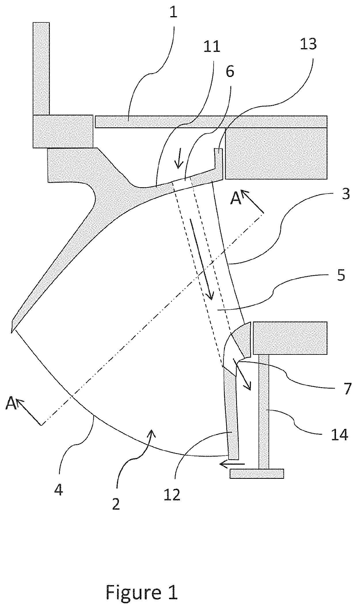
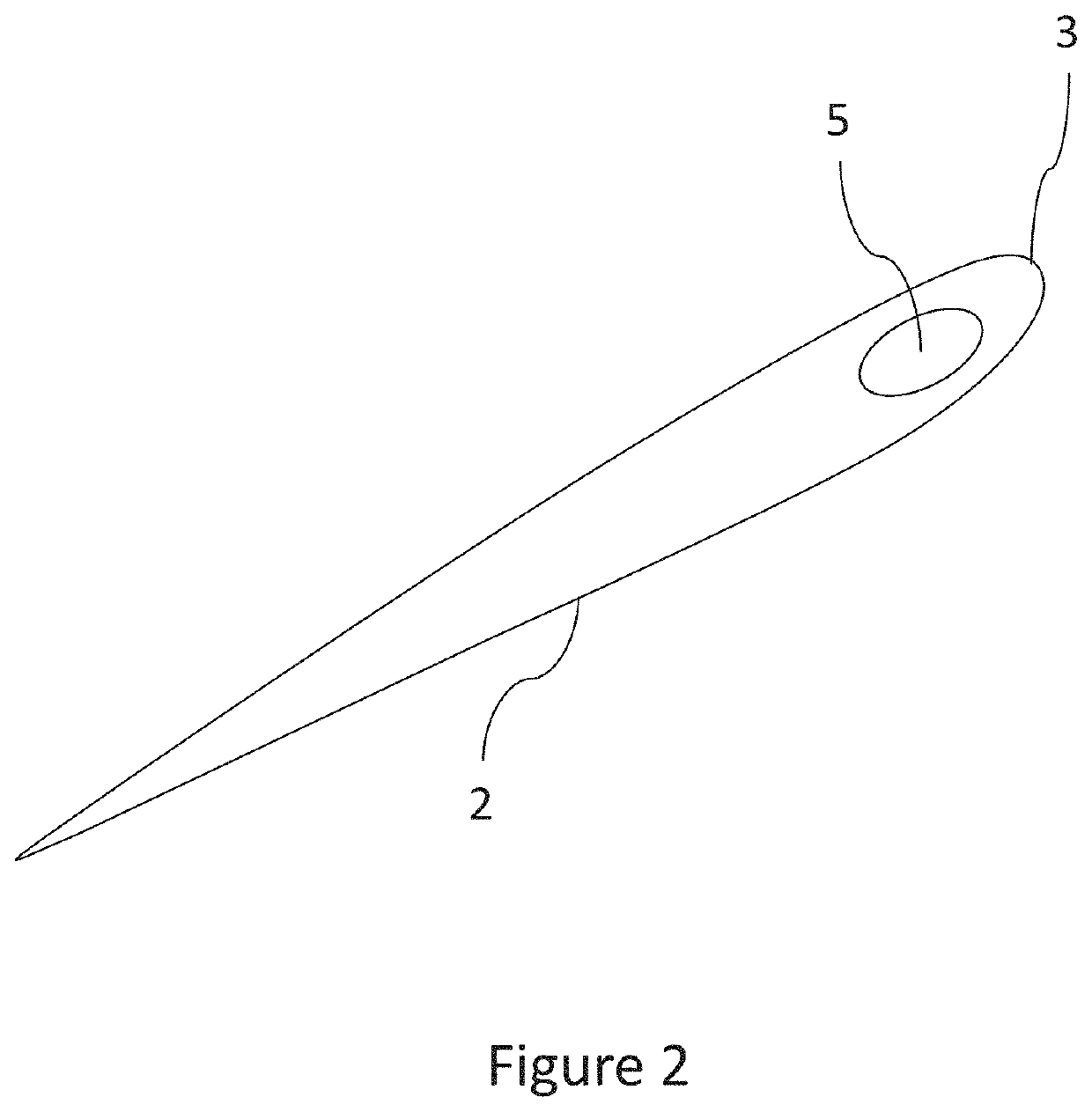
[0014]Referring now to the drawings and more particularly to FIG. 1 there is shown in a schematic form a cross-sectional view of a hydraulic machine including an embodiment of a Francis type runner according to the present invention. The head cover is designated as 1 and the lower cover as 14. The runner includes a runner crown 11. A runner blade 2 extends between runner crown 11 and a band 12. Runner blade 2 has two edges designate by 3 and 4. The fluid entering the runner flows from edge 3 towards edge 4, whereas the high-pressure side adjoins to edge 3 and the low-pressure side adjoins to edge 4. In a pumping mode the flow direction of the fluid is reversed. Runner crown 11 includes a circumferential located sealing element 13. Sealing elements 13 are construed to seal the space between head cover 1 and crown 11 against high-pressure water. However due to the imperfection of the sealing a small amount of high-pressure water will be present in the space above runner crown 11 leadi...


PUM


Abstract

A hydraulic machine including a runner of Francis type, a head cover and a lower cover, the runner includes a low and a high pressure side, a crown, a band, and a plurality of blades, the crown having a sealing element to seal the space between the crown and head cover against water from the high-pressure side, whereas the runner has at least one passage to drain high-pressure leakage water passing the sealing element to the low-pressure side, and the passage has an inlet aperture located in a portion of the crown which during operation is exposed to high-pressure leakage water, the passage being located within one of the blades and leads from the inlet aperture to the band, where the passage forms an opening leading to the space between the band and the lower cover.

Description

CROSS REFERENCE TO RELATED APPLICATIONS[0001]This is a continuation of PCT application No. PCT / EP2017 / 081661, entitled “HYDRAULIC MACHINE COMPRISING A RADIAL FLOW RUNNER”, filed Dec. 6, 2017, which is incorporated herein by reference. PCT application No. PCT / EP2017 / 081661 is a non-provisional application based upon U.S. provisional patent application Ser. No. 62 / 449,835, entitled “RUNNER FOR A HYDRAULIC TURBINE OR PUMP”, filed Jan. 24, 2017, U.S. provisional patent application Ser. No. 62 / 519,472, entitled “RADIAL FLOW RUNNER FOR A HYDRAULIC MACHINE”, filed Jun. 14, 2017, and U.S. provisional patent application Ser. No. 62 / 545,135, entitled “HYDRAULIC MACHINE COMPRISING A RADIAL FLOW RUNNER”, filed Aug. 14, 2017, which are incorporated herein by reference.BACKGROUND OF THE INVENTION1. Field of the Invention[0002]The present invention relates generally to hydroelectric turbine or pump installations that include a radial flow runner of the Francis type.2. Description of the Related Ar...

Claims


Application Information

Patent Timeline
Patent Type & Authority Patents(United States)
IPC IPC(8): F03B3/12F03B3/02F03B11/00F04D3/00F04D29/16
CPCF03B3/125F03B3/02F03B11/006F04D3/005F04D29/168F05B2220/32Y02E10/20
Inventor COULSON, STUART
Owner VOITH PATENT GMBH
Why Eureka
Try Eureka