Seat for vehicle

a seat and vehicle technology, applied in the field of seats for vehicles, can solve the problems of dimensional accuracy that cannot be secured by laser welding, and achieve the effect of improving mass productivity and rigidity of seat back frames

Active Publication Date: 2021-04-20
TACHI S CO LTD
View PDF14 Cites 0 Cited by
  • Summary
  • Abstract
  • Description
  • Claims
  • Application Information

AI Technical Summary

Benefits of technology

[0004]The present inventors have executed studies for improving the torsional rigidity of a seat back. According to the studies, it has been found that a seat back frame using an upper frame having a hat-shape cross section opening rearward has lower torsional rigidity compared to a pipe structure because the upper frame has an open cross section. Therefore, there is a case that rigidity required for a seat back frame is not secured unless the shape of the component of the upper frame having the hat-shape cross section is made complicated and enlarged and is made to have a thicker thickness in order to improve the torsional rigidity of a seat back frame using the upper frame having the hat-shape cross section opening rearward.
[0006]The object of the present invention is to provide a seat for vehicle including a back frame having a panel structure improving torsional rigidity and allowing welding.
[0010]According to the seat for vehicle described above, rigidity of the seat back frame can be improved. Also, according to the seat for vehicle described above, mass productivity can be improved.

Problems solved by technology

However, there is a case that dimensional accuracy allowing laser welding is hardly secured.

Method used


Image

  • Seat for vehicle
  • Seat for vehicle
  • Seat for vehicle

Examples


first embodiment

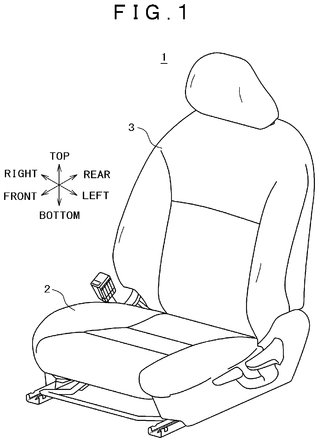
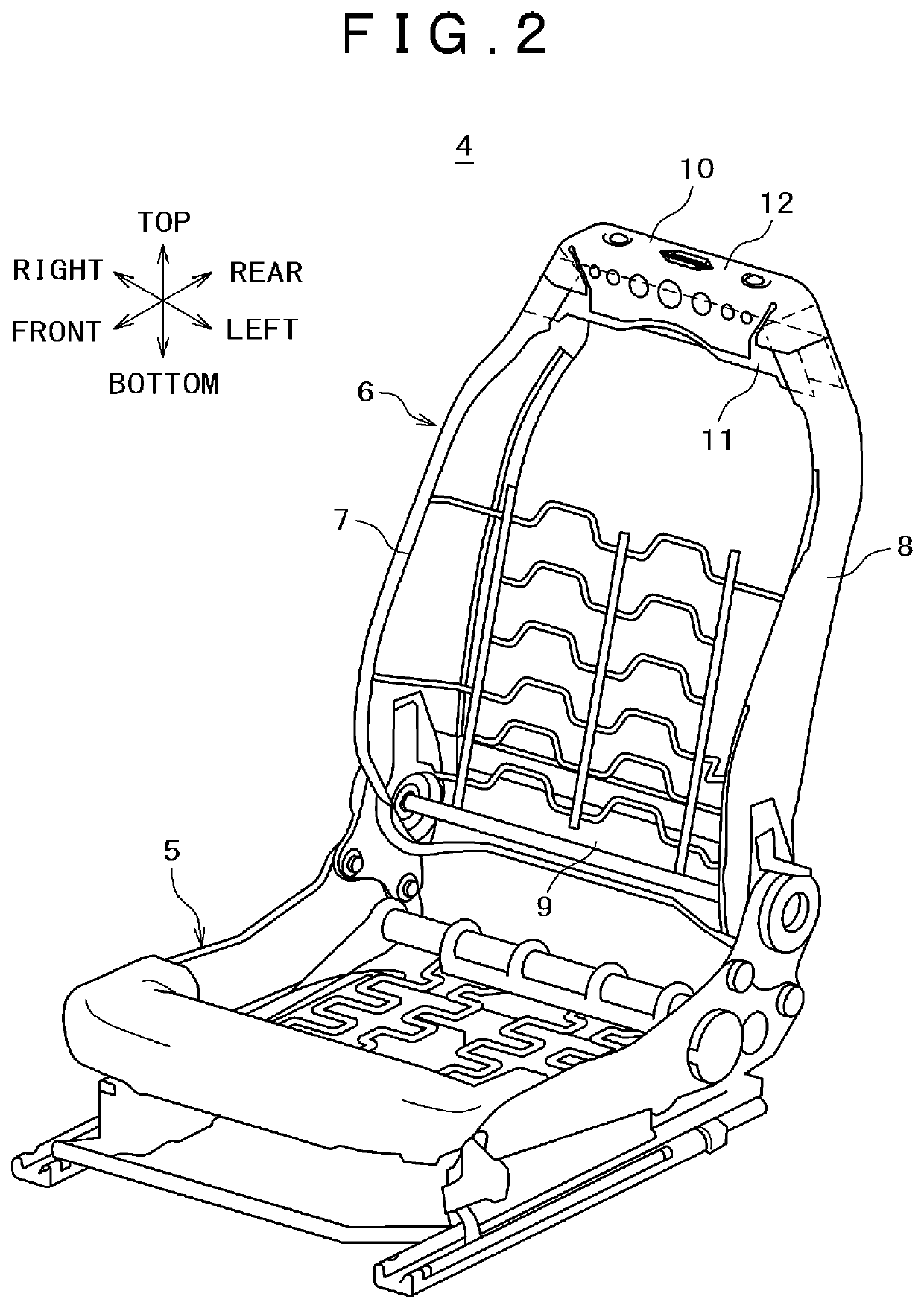
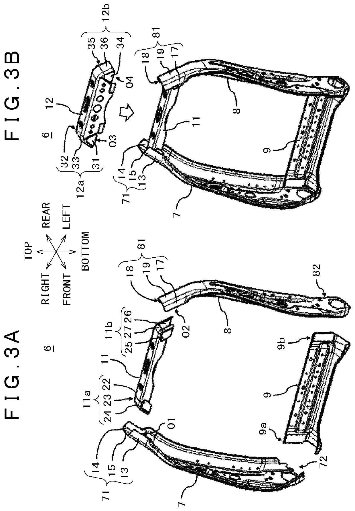
[0026]FIG. 1 is a front perspective view of a seat for vehicle related to the first embodiment. FIG. 2 is a front perspective view of a seat frame of the seat for vehicle shown in FIG. 1. FIG. 3A and FIG. 3B are drawings for explaining a seat back frame, FIG. 3A is a drawing for explaining assembling of left and right side frames, a lower frame, and a first upper frame, and FIG. 3B is a drawing for explaining assembling of a second upper frame. FIG. 4A, FIG. 4B, and FIG. 4C are drawings for explaining assembling of the left and right side frames and the first and second upper frames, FIG. 4A is a front surface enlarged view of the upper part of the seat back frame, FIG. 4B is a cross-sectional view along the line A-A shown in FIG. 4A, and FIG. 4C is a cross-sectional view along the line B-B shown in FIG. 4A. FIG. 5A and FIG. 5B are drawings for explaining a welding position of the left and right side frames and the first and second upper frames, FIG. 5A is a front enlarged view of t...

second embodiment

[0053]The second embodiment has a configuration that, behind the upper frame 10 having a cross-sectional shape of a hat shape, a bracket 40 like a rectangular flat sheet member for example is fixed so as to connect upper and lower flanges (10c, 10d) of the recessed part having a cross-sectional shape of a hat shape, and torsional rigidity of the back frame 6 is improved. Below, the second embodiment will be explained using FIG. 6A, FIG. 6B, FIG. 7A, and FIG. 7B. Further, although the bracket 40 is shown illustratively as a rectangular flat sheet member, it only has to be a fixing member that can connect the upper and lower flanges (10c, 10d) of the recessed part having a cross-sectional shape of a hat shape.

[0054]FIG. 6A and FIG. 6B are drawings for explaining the back frame 6 related to the second embodiment, FIG. 6A is a drawing for explaining assembling of the left and right side frames, the lower frame, the upper frame, and the bracket, and FIG. 6B is a front perspective view of...


PUM


Abstract

A seat for vehicle includes a seat cushion and a seat back. A seat back frame of the seat back includes a right side frame, a left side frame, a lower frame, and an upper frame. The upper frame includes a first upper frame and a second upper frame, the first upper frame having a cross-sectional shape of a U-shape opening downward, the second upper frame having a cross-sectional shape of a U-shape opening downward, and a closed cross section is configured by vertically overlaying the first upper frame and the second upper frame.

Description

CLAIM OF PRIORITY[0001]The present application claims priority from Japanese Patent Application JP 2018-109649 filed on Jun. 7, 2018, the content of which is hereby incorporated by reference into this application.BACKGROUND OF THE INVENTIONTechnical Field[0002]The present invention relates to a seat for vehicle, and can be applied to a seat for vehicle including a seat back frame in particular.Background Art[0003]A seat for vehicle includes a seat cushion and a seat back, and a seat back frame that configures the seat back is configured by combining a left and right side frames, a lower frame, and an upper frame into a frame shape by welding and the like. There is a case that the upper frame of this kind is configured by a steel sheet that is press-formed to have a hat-shape cross section opening rearward (refer to JP-A No. 2015-67133). Also, there is a case that a seat back frame is configured by bending a round pipe (refer to JP-A No. 2017-77801).SUMMARY OF THE INVENTION[0004]The ...

Claims


Application Information

Patent Timeline
Patent Type & Authority Patents(United States)
IPC IPC(8): B60N2/68B60N2/64
CPCB60N2/68B60N2/64B60N2205/20
Inventor KUBOTA, HIDEKAZUKANEKO, MASARUFUKUSHIMA, HIROSHI
Owner TACHI S CO LTD
Why Eureka
Try Eureka