Wire protecting protector and protector-equipped wire

a technology for protecting wires and wires, which is applied in the direction of electrical/fluid circuits, vehicle components, electrical apparatus, etc., can solve the problems of heavy considerable constraints on the production process, etc., and achieve the effect of reducing the weight of the protective wire, reducing the constraints on the mounting, and facilitating external for

Active Publication Date: 2021-04-20
SUMITOMO WIRING SYST LTD
View PDF13 Cites 0 Cited by
  • Summary
  • Abstract
  • Description
  • Claims
  • Application Information

AI Technical Summary

Benefits of technology

[0020]According to the first aspect, the wire protecting protector is made of a foamed resin, and it is therefore possible to reduce the weight thereof. Furthermore, the surface of the wire protecting protector that includes the inner circumferential surface on the wire housing recess side is a surface formed through molding, and it is therefore possible to house a wire in the wire housing recess and protect the wire, after producing the wire protecting protector. Accordingly, it is possible to reduce the constraints on the mounting of the wire protecting protector to the wire.
[0021]According to the second aspect, it is possible to protect the entire periphery of a wire by closing the opening of the main body portion with the cover portion after housing the wire inside the wire housing recess of the main body portion.
[0022]According to the third aspect, it is possible to attach the cover portion to the main body portion by fitting the fitting protrusion to the fitting recess.
[0023]According to the fourth aspect, the reinforcing film is formed on at least a part of the surface of the wire protecting protector, and it is therefore possible to reinforce the wire protecting protector made of a foamed resin.
[0024]According to the fifth aspect, it is possible to reinforce the thinned portion with the reinforcing film.
[0025]According to the sixth aspect, it is possible to reinforce the force receiving portion with the reinforcing film, thus making it possible to more easily withstand an external force.

Problems solved by technology

However, the technique disclosed in Patent Document 1 is problematic in that the protector, which is a resin molded component, is heavy.
Also, the technique disclosed in Patent Document 2 poses the problem of considerable constraints on the production process because the wire harness is molded through resin molding into a routing configuration, with the wire group inserted into the groove of the mold.

Method used


Image

  • Wire protecting protector and protector-equipped wire
  • Wire protecting protector and protector-equipped wire
  • Wire protecting protector and protector-equipped wire

Examples


Embodiment Construction

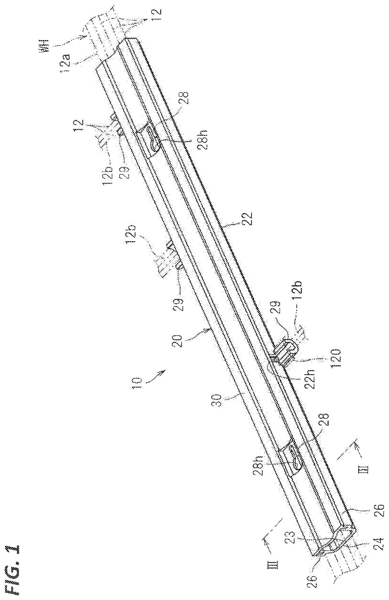
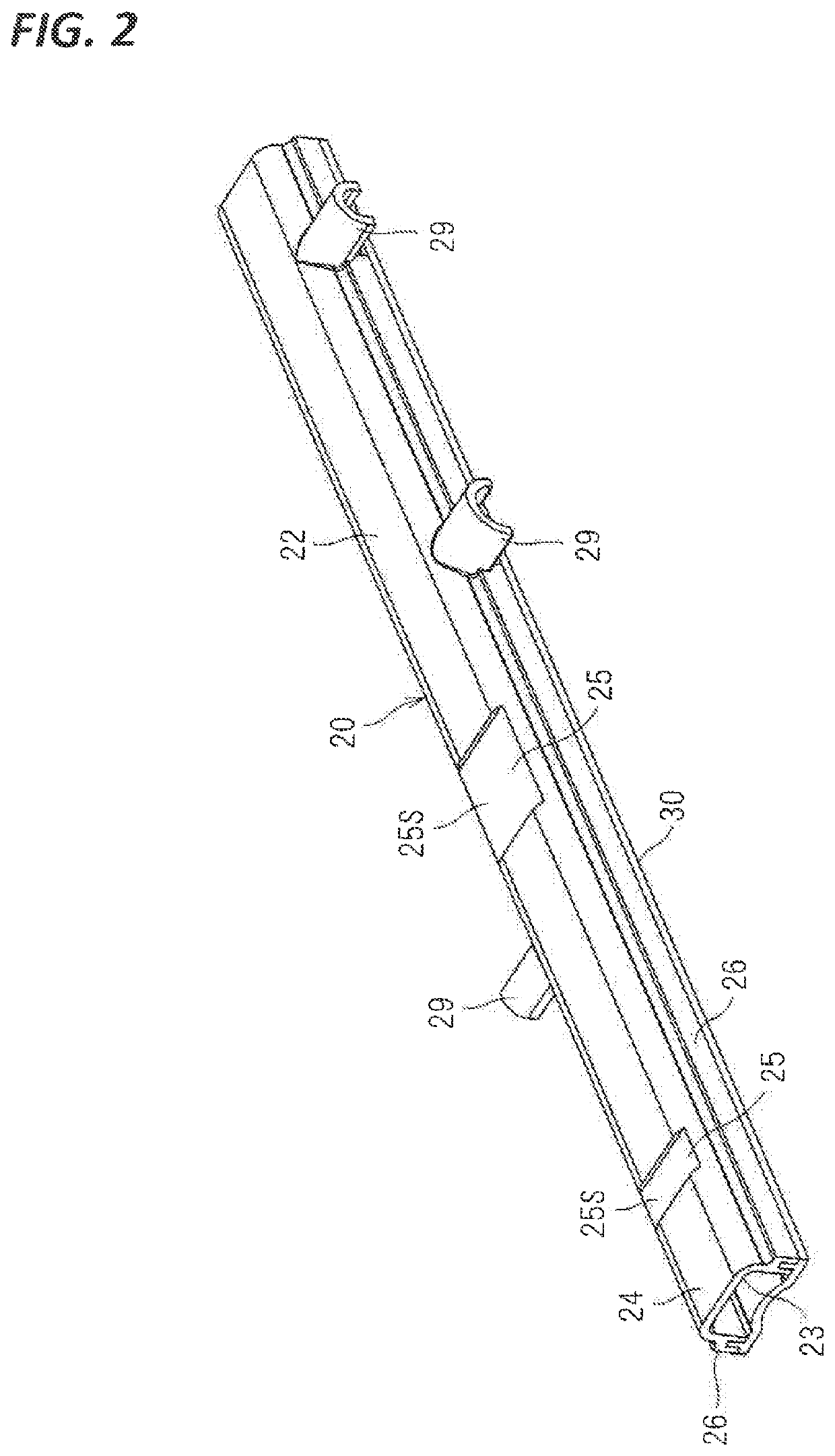
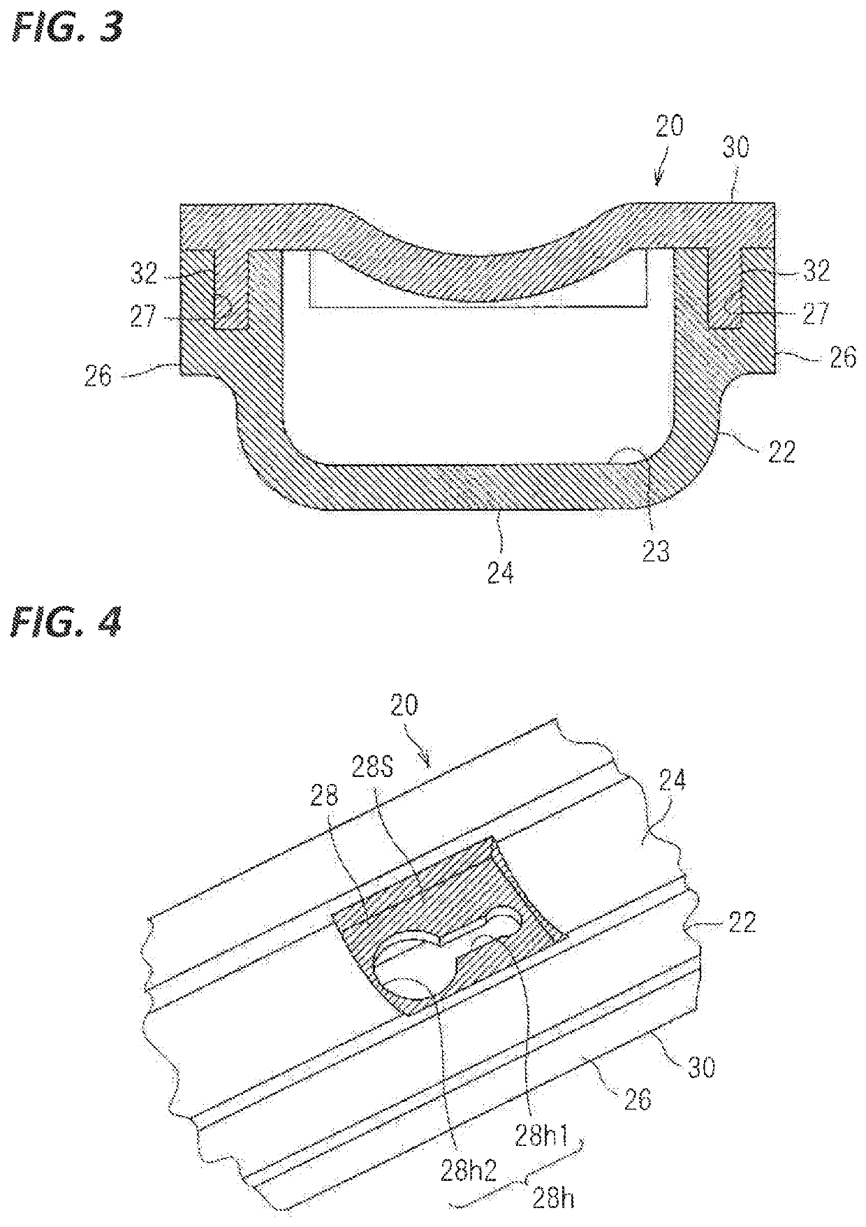
[0043]Hereinafter, a wire protecting protector and a protector-equipped wire according to an embodiment will be described. FIG. 1 is a schematic perspective view showing a protector-equipped wire 10, FIG. 2 is a perspective view showing a wire protecting protector 20, FIG. 3 is a cross-sectional view taken along the line II-II in FIG. 1, FIG. 4 is a partial enlarged view of FIG. 1, and FIG. 5 is a partial enlarged view of FIG. 2.

[0044]The protector-equipped wire 10 includes a wire 12 and a wire protecting protector 20.

[0045]The wire 12 includes a coating portion formed, for example, by extrusion coating a resin on the outer circumference of a core wire. Here, a plurality of wires 12 are bundled to form a wire bundle 12a. Some of the wires are branched in an intermediate part of the wire bundle 12a in the extension direction thereof, thus forming branched portions 12b. Here, the wire protecting protector 20 houses and protects the intermediate part of the wire bundle 12a in the exten...


PUM


Abstract

An object of the present invention is to reduce the constraints on the mounting of a wire protecting protector to a wire, while achieving a reduction in the weight of the wire protecting protector. A wire protecting protector is made of a foamed resin and is formed in a shape having a wire housing recess capable of housing a wire, and a surface of the wire protecting protector that includes an inner circumferential surface on the wire housing recess side is a surface formed through molding. Preferably, a reinforcing film is formed on at least a part of the surface of the wire protecting protector.

Description

CROSS REFERENCE TO RELATED APPLICATIONS[0001]This application is a national phase of PCT application No. PCT / JP2018 / 011278, filed on 22 Mar. 2018, which claims priority from Japanese patent application No. 2017-055404, filed on 22 Mar. 2017, all of which are incorporated herein by reference.TECHNICAL FIELD[0002]The present invention relates to a technique for protecting wires.BACKGROUND[0003]Patent Document 1 discloses a technique for protecting wires using a protector that is a resin molded component obtained through molding or the like.[0004]Patent Document 2 discloses a wire harness that has been molded into a routing configuration through resin molding, with a group of wires inserted into a groove of a mold. Patent Document 2 also discloses filling a part of the groove with a urethane foam.PRIOR ART DOCUMENTPatent Document[0005]Patent Document 1: JP 2013-212005A[0006]Patent Document 2: JP 2004-006126ASUMMARY OF THE INVENTIONProblems to be Solved[0007]However, the technique discl...

Claims


Application Information

Patent Timeline
Patent Type & Authority Patents(United States)
IPC IPC(8): H02G3/04
CPCH02G3/0487B60R16/0215H02G3/0418H02G3/0437
Inventor IDE, TAKASHIYONEKAWA, JUNYASAKATA, TSUTOMUNAGAYASU, DAIKI
Owner SUMITOMO WIRING SYST LTD
Why Eureka
Try Eureka