
Time-of-flight imaging device, system and method

a technology of imaging device and time-of-flight, applied in the field of imaging system, can solve the problems of silicon area and silicon area, and achieve the effect of reducing the cost of silicon area

Active Publication Date: 2021-05-04
STMICROELECTRONICS (RES & DEV) LTD
View PDF2 Cites 2 Cited by
  • Summary
  • Abstract
  • Description
  • Claims
  • Application Information

AI Technical Summary

Benefits of technology

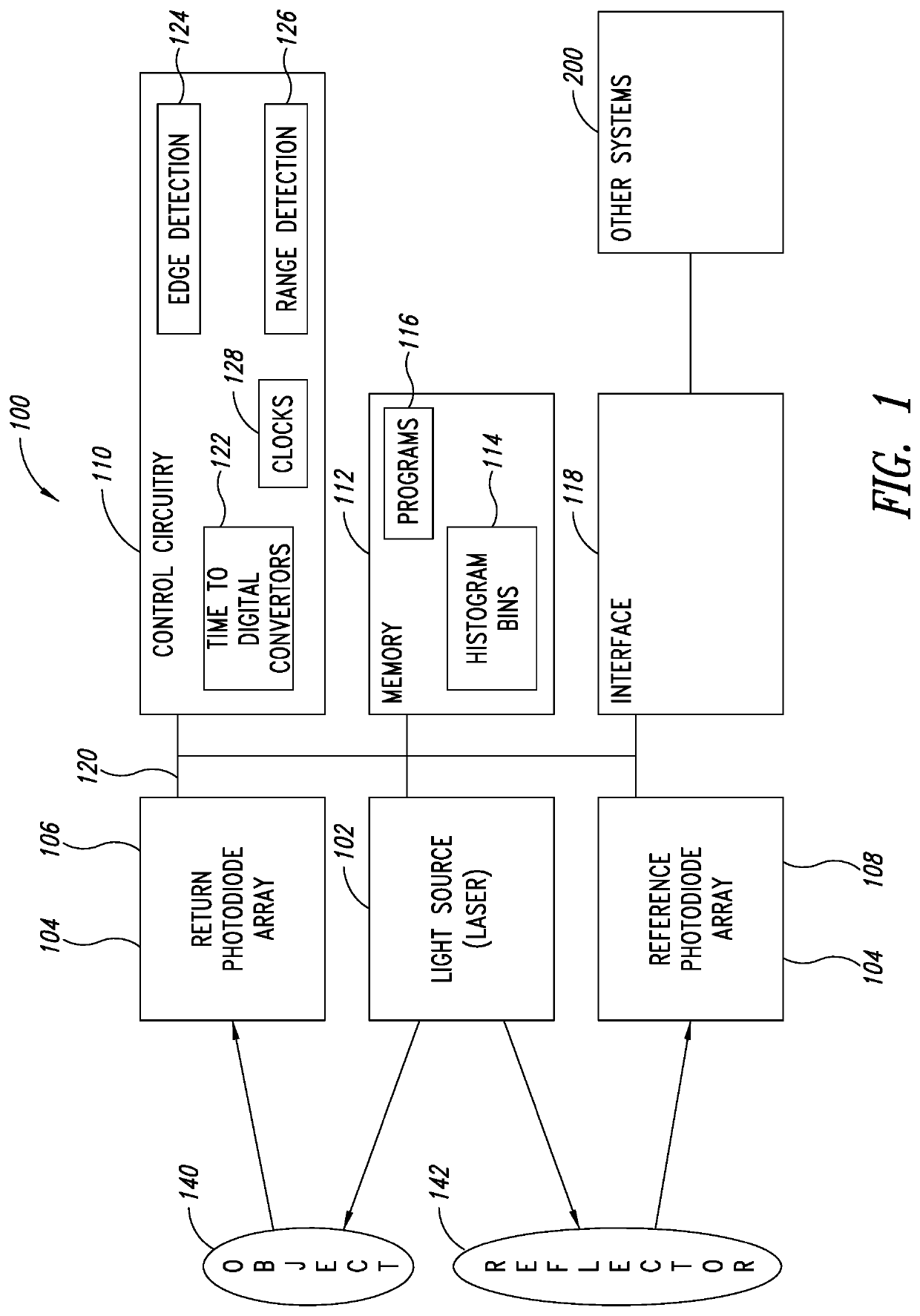
The patent describes a method for using a time-of-flight (TOF) image sensor to generate an image of objects in an environment and measure the distances between them. The method involves illuminating the objects and analyzing the reflections from them to generate counts that are stored in a histogram. The histogram includes a plurality of bins, with each bin associated with a specific distance range. The size of each bin is determined by a logarithmic function of the distance range. The method can be implemented using a reference reflector and digital-to-time converters. The system can also include an automotive control circuitry for controlling the vehicle based on the generated image data. The technical effect of the patent is to provide a reliable and accurate method for measuring distances to objects in an environment using aTOF image sensor.

Problems solved by technology

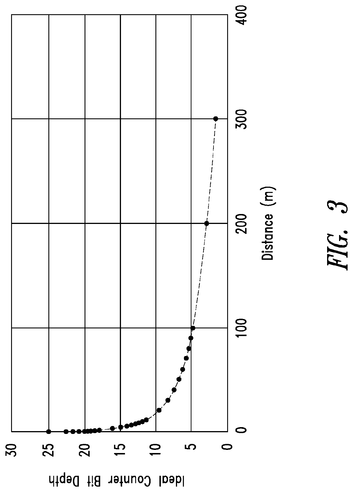
To store multiple time slices or depth points the histogram must have many bins, which may present a considerable cost in terms of silicon area.

Method used


Image

  • Time-of-flight imaging device, system and method
  • Time-of-flight imaging device, system and method
  • Time-of-flight imaging device, system and method

Examples


Embodiment Construction

[0014]In the ensuing description, one or more specific details are illustrated, aimed at providing an in-depth understanding of examples of embodiments of this description. The embodiments may be obtained without one or more of the specific details, or with other methods, components, materials, etc. In other cases, known structures, materials, or operations are not illustrated or described in detail so that certain aspects of embodiments will not be obscured.

[0015]Reference to “an embodiment” or “one embodiment” in the framework of the present description is intended to indicate that a particular configuration, structure, or characteristic described in relation to the embodiment is comprised in at least one embodiment. Hence, phrases such as “in an embodiment” or “in one embodiment” that may be present in one or more points of the present description do not necessarily refer to one and the same embodiment. Moreover, particular conformations, structures, or characteristics may be com...


PUM


Abstract

A time-of-flight (TOF) imaging system includes illumination circuitry, such as a laser, one or more sensors, such as SPAD arrays, and image processing circuitry. The illumination circuitry illuminates one or more objects in an environment around the TOF imaging system. The sensors generate an image data stream based on reflections from the one or more illuminated objects, and possibly based on reflections from one or more reflectors. The image processing circuitry generates counts associated with distances based on the image data stream and possibly a reflection data stream and stores the generated counts in a histogram using a plurality of bins. Each of the plurality of bins stores counts associated with a respective distance range. A size of a bin in the plurality of bins is a function of the respective distance range, and may be based on a logarithmic function of the distance associated with the bin.

Description

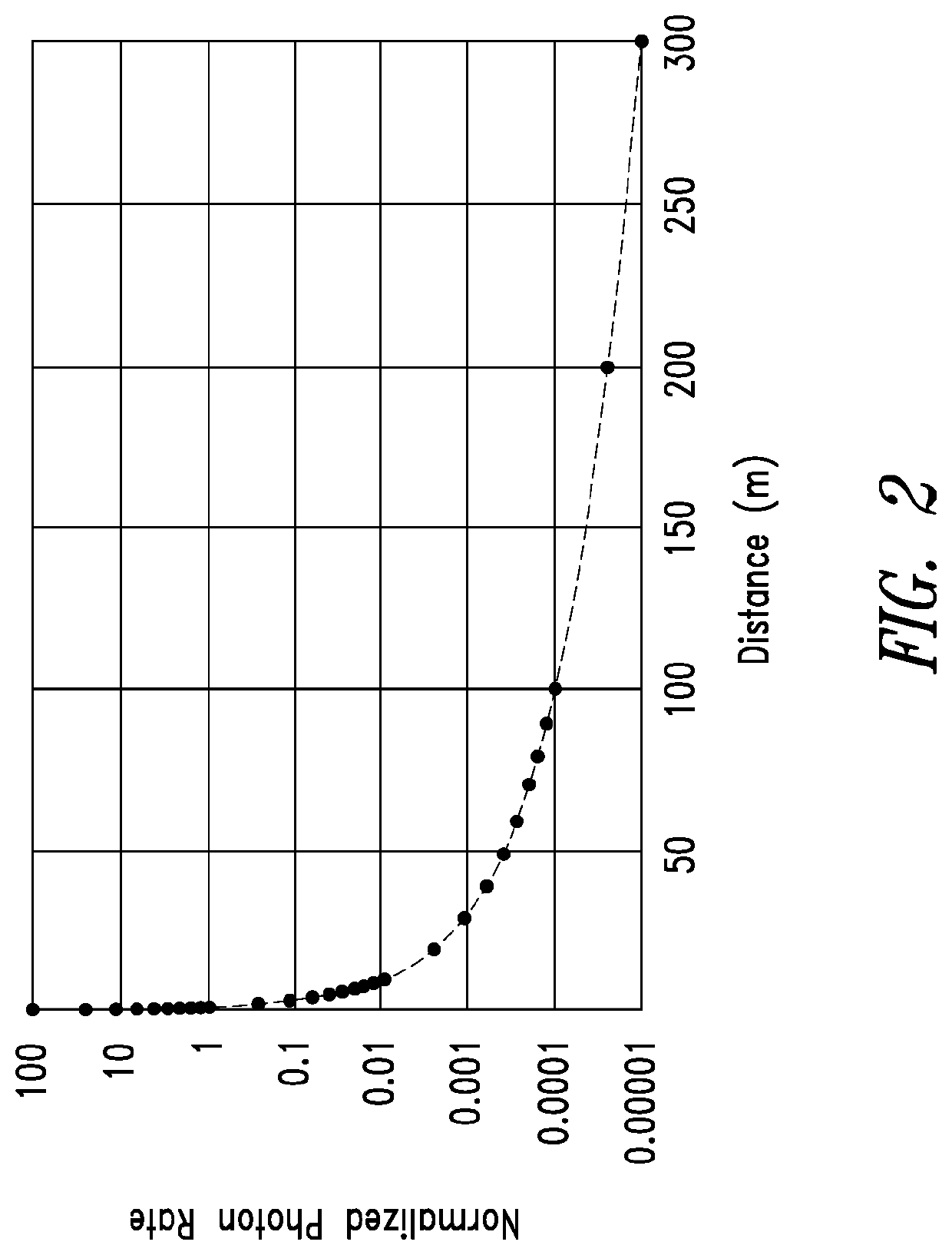
BACKGROUNDTechnical Field[0001]The present description relates to imaging systems, such as Time-of-Flight (TOF) imaging systems including Light Detection and Ranging (LIDAR) systems, which may be used, for example, in automotive applications.Description of the Related Art[0002]TOF systems, such as LIDAR systems are used in a number of applications, including range finding, depth profiling, 3-D imaging, automotive applications, etc. TOF Image processing techniques often employ histograms, for example, to control the imaging system, to store and process received image data, etc.[0003]For example, a time-domain histogram of a scene spanning a large distance range (e.g., from 1 meter to 300 meters) may create a massive dynamic range of returned photon flux having a difference of many orders of magnitude. Time-to-Digital Converters (TDCs) with direct histogram outputs may have very high data rates and may capture a time-domain histogram of a single spatial point or pixel. To store multip...

Claims


Application Information

Patent Timeline
Patent Type & Authority Patents(United States)
IPC IPC(8): G01C3/08G01S7/4863G01S17/14G01S17/894G01S17/931
CPCG01S7/4863G01S17/14G01S17/894G01S17/931
Inventor PATANWALA, SARRAH MOIZDUTTON, NEALE
Owner STMICROELECTRONICS (RES & DEV) LTD
Learn More