Bone staple inserter

a technology of inserters and staples, applied in the field of inserters, can solve problems such as problems in the use and design of deployment instruments or inserters, and achieve the effects of preventing inadvertent disassembly, quick and efficient use, and minimal user interaction

Active Publication Date: 2021-05-11
ORTHO SOLUTIONS HLDG LTD
View PDF64 Cites 0 Cited by
  • Summary
  • Abstract
  • Description
  • Claims
  • Application Information

AI Technical Summary

Benefits of technology

[0004]The invention provides an inserter for a superelastic compressive bone staple. A preferably configuration for the bone staple is a substantially U-shaped staple, i.e. a staple having a transverse bridge member and downwardly extending legs, which can be biased into a parallel “activated position” for insertion into the bone, and then released into a compressive configuration. Thus, the inserter is advantageously pre-assembled (i.e. prior to surgery) with a “U-shaped” or modified “table top” style staple in a non-activated state (i.e. in which the legs converge toward each other, each at an angle of from 60° to 88°, and preferably at an angle from 70° to 85° relative to an axis along the bridge member of the staple) and includes an easy to use mechanism for “activating” the staple by deforming the legs to a transverse position and initiating the super elastic properties of the staple material.
[0008]In accordance with the invention, a staple is supplied preassembled (on a disposable inserter) as part of a sterile packed procedure kit. The staple is not pre-loaded, which means that the staple is not subjected to the mechanical deformation which initiates the superelastic characteristics of the staple. The staple introducer provides quick and efficient use with minimal user interaction which is accomplished by constraining the staple on the inserter on the pair of cylindrical pins which form a part of an expander component of the inserter and which expands the staple legs to a 90° insertion position. The staple is further captured on the inserter and prevented from inadvertent disassembly from the inserter by a ramp that acts as a cover in the resting or non-energised position.
[0009]The cylindrical expander pins of the inserter retain the staple in a non-preloaded / non-energized position but interface with the staple in the proximal corners. This captures the staple securely on the inserter, and permits the activation of the staple for deployment. The design also enables use of the inserter with both symmetrical and asymmetrical leg staples. Moreover, retaining the staple in the proximal corners also ensures that the majority of the staple leg length is available for inserting on to the bones prior to low profile as possible to minimize packaging footprint and to prevent impingement with surrounding anatomy during use.

Problems solved by technology

While the state of the art has advanced the use of bone staples, there remain issues in the use and design of the deployment instrument or inserter.

Method used


Image

  • Bone staple inserter
  • Bone staple inserter
  • Bone staple inserter

Examples


Embodiment Construction

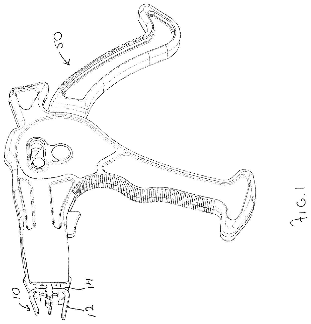
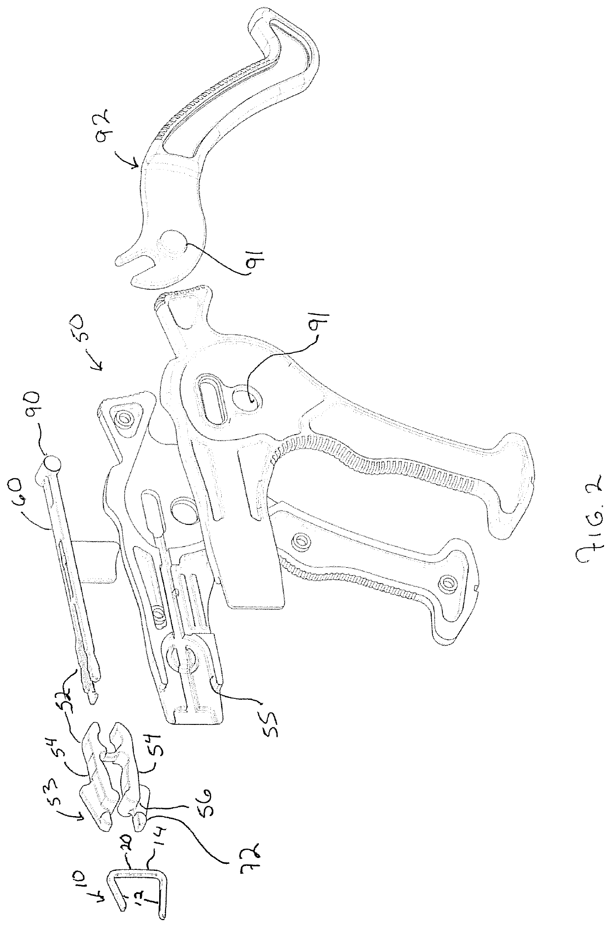
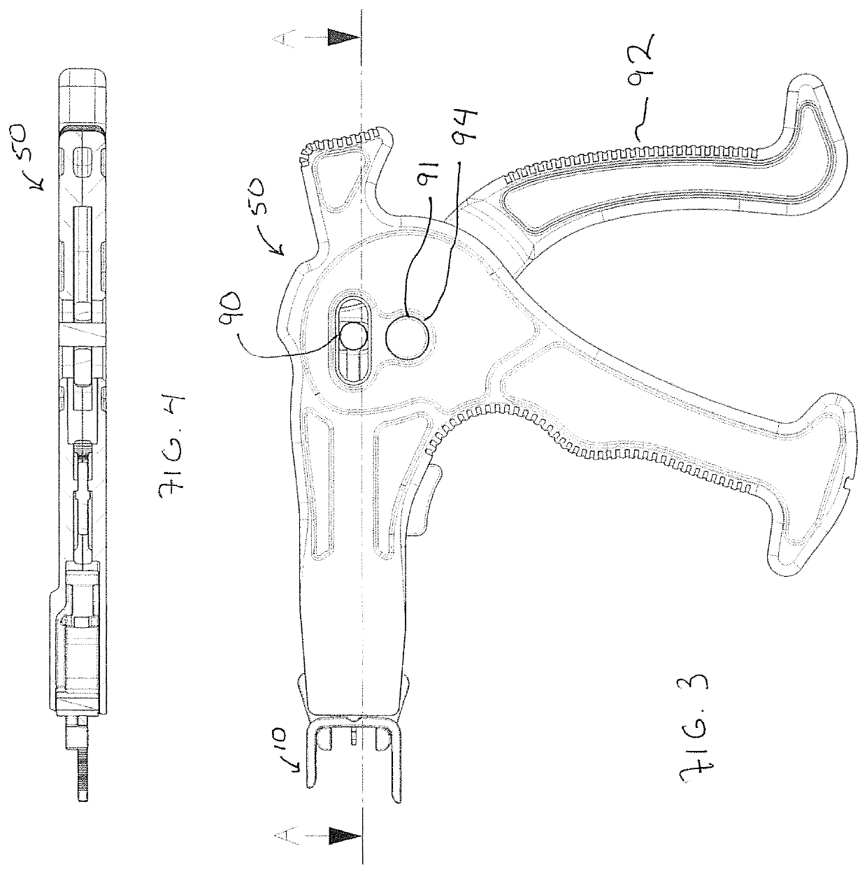
[0026]The product comprises an inserter 50 for use with a room temperature superelastic Nitinol compression staple 10 for bone fixation in the surgical management of fractures and reconstruction of the foot and hand. Typically, the staples used with the present invention have a nominally U-shaped profile with a bridge member 14 spanning a space between opposing legs 12 (and it should be understood that the present inserter is also suitable for use with a staple having four legs in which each end of the bridge member includes a pair of legs, or alternatively, the staple could have three legs with a pair on one end, and a single leg opposing the pair.)

[0027]The staple 10 has two or more, and preferably 2, 3, or 4 transversely extending legs 12 that will engage bones or bone segments through the cortical surfaces. The legs 12 are spaced apart from each other and joined together by bridge member 14 that extends across the area between legs at either end of the bridge member 14. As shown...


PUM


Abstract

The invention is an inserter for a staple having a bridge member and opposing open legs and the inserter holds the staple between a pair of cylindrical expanders which splay apart in response to a camming mechanism having a pair of followers that carry the expanders. The followers are activated as they are drawn over the camming ramp in response to a trigger action. The ramp also includes a detent which alerts the user that the staple is engaged in an activated position, and a safety that keeps the followers from returning to the un-loaded position.

Description

FIELD OF THE INVENTION[0001]The invention comprises an inserter for use with a room temperature superelastic Nitinol staple intended for bone fixation in the surgical management of fractures and reconstruction of the foot and hand. The staple has a bridge member that extends a length along an axis and which joins legs spaced apart along the axis. The inserter can be used with a staple having two, three, or four legs (i.e. two pairs of legs spaced apart along the axis). The staple is fabricated in a closed (converging legs) shape and is mechanically deformed or “activated” by the inserter during use to induce the superelastic shape memory properties in the staple so as to compress bone segments and facilitate osteosynthesis in use. The staple is held on the inserter on cylindrical expanders and the inserter has a mechanism to spread the expanders which opens the legs so that the superelastic properties are induced and the legs are spread into transverse positions for implantation. Th...

Claims


Application Information

Patent Timeline
Patent Type & Authority Patents(United States)
IPC IPC(8): A61B17/10A61B17/064A61B17/068A61B90/00A61B17/00
CPCA61B17/10A61B17/0642A61B17/0682A61B2017/00367A61B2017/00867A61B2017/0645A61B2090/0811
Inventor STAMP, KEVIN
Owner ORTHO SOLUTIONS HLDG LTD
Why Eureka
Try Eureka