Set of floor panels for forming a floor covering

a technology of floor panels and floor coverings, applied in flooring, construction, building construction, etc., can solve the problems of difficulty in forming complementary fittings, moisture or dust penetrating between the coupled edges of floor panels, and difficulty in installation, so as to minimize the risk of moisture and dust penetrating the floor panels. , the effect of facilitating installation

Active Publication Date: 2021-05-11
FLOORING IND LTD
View PDF82 Cites 3 Cited by
  • Summary
  • Abstract
  • Description
  • Claims
  • Application Information

AI Technical Summary

Benefits of technology

[0014]The inventor has found that a maximum bending of at most 0.0625 times the overall thickness of the floor panel allows effectively counteracting the forming of gaps between the coupled edges and in this manner minimizing or even excluding the risk of penetrating moisture and dust. Therein, moreover it has become apparent that the floor panels, although they are provided with a pretension, still can be coupled to each other in a smooth manner.
[0067]In view of the fact that the present invention allows minimizing the risk of penetrating moisture and dust, it is primarily applied in an advantageous manner with floor panels, the core of which is at least partially composed of wood-based materials, such as MDF, HDF, or Wood Plastic Composite or WPC.

Problems solved by technology

A general problem with the known sets of floor panels as described above is the risk of moisture or dust penetrating between the coupled edges of the floor panels.
However, there is a risk that difficulties will be experienced when coupling the floor panels which are provided with pretension.
In order to be able to realize the pretension, the profile shapes or the contours of the coupling parts in fact have to be made overlapping, and thus they are not complementary fitting.
Moreover, the coupling movement can be complicated further by the almost unavoidable tolerances of the perpendicularity of the sides of the floor panels.
Therefore, the coupling parts in practice mostly are configured such that they fit into each other with a certain play, which in its turn then entrains the risk of moisture and dust penetrating between the coupled edges.
In that such insertion piece has to be provided, the floor panels of WO '605 are not cheap.
However, such groove can have a detrimental influence on the stability of the lip of the receiving hook and consequently on the tensioning force supplied by the lip.

Method used


Image

  • Set of floor panels for forming a floor covering
  • Set of floor panels for forming a floor covering
  • Set of floor panels for forming a floor covering

Examples


Embodiment Construction

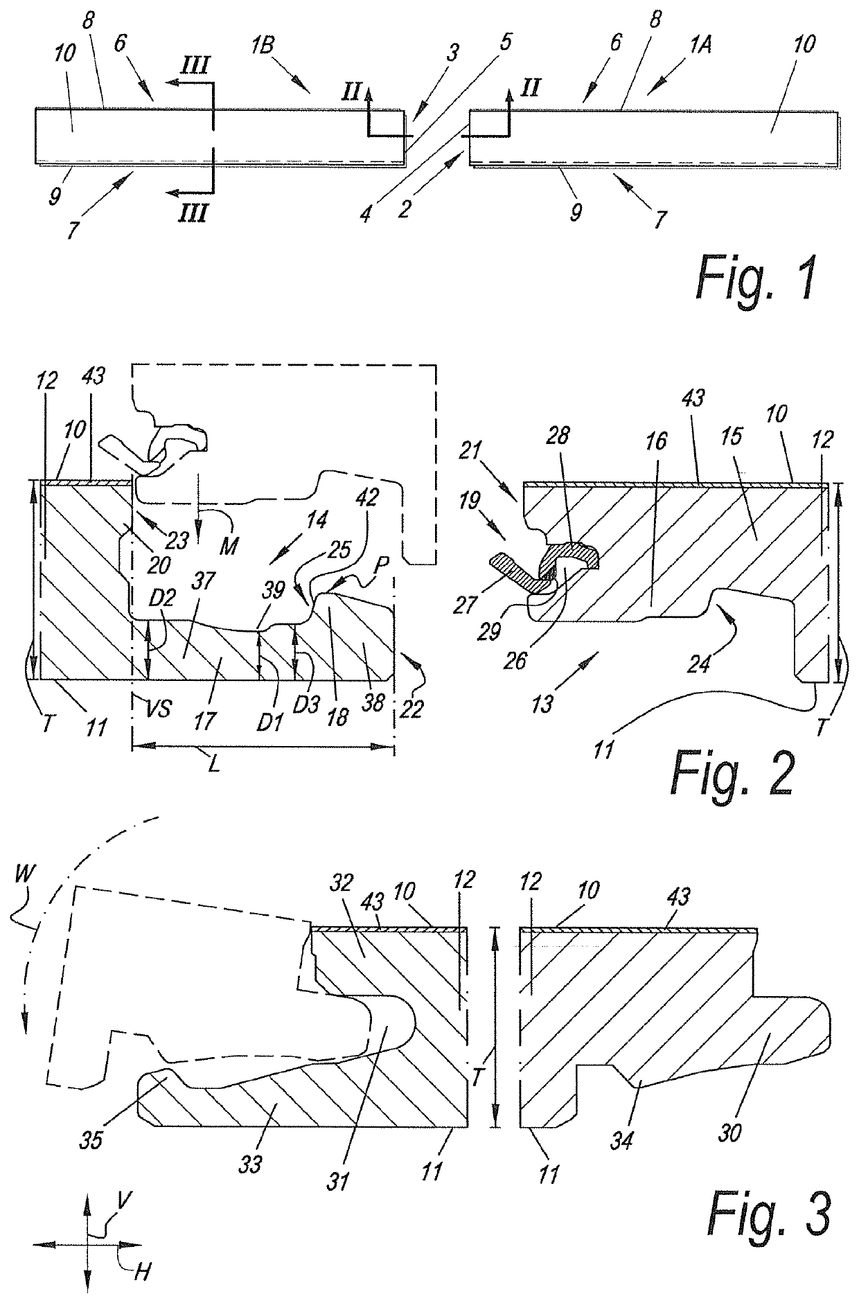
[0080]FIG. 1, in top view, represents a set of floor panels 1A-1B for forming a floor covering, wherein the floor panels 1A-1B here are oblong rectangular and thus comprise a pair of short sides and a pair of long sides. The floor panels 1A-1B are represented in a not-coupled or not-installed condition.

[0081]The opposite short sides of the floor panels 1A-1B form edges 2-3 which are provided with coupling parts 4-5. Although here opposite edges 2-3 of two floor panels 1A-1B are concerned, it is clear that these edges 2-3 can also relate to edges of one and the same floor panel, which then relate to opposite edges of that floor panel.

[0082]The long sides of the floor panels 1A-1B form edges 6-7, which are provided with coupling parts 8-9.

[0083]FIG. 2 represents a cross-section according to line II-II in FIG. 1. Thus, FIG. 2 represents a cross-section wherein the coupling parts 4-5 on the short sides of the floor panels 1A-1B are visible.

[0084]The floor panels 1A-1B each comprise an u...


PUM

PropertyMeasurementUnit
angleaaaaaaaaaa
angleaaaaaaaaaa
angleaaaaaaaaaa

Abstract

A set of floor panels for forming a floor covering, which comprises at least two floor panels, which each comprise an edge provided with a coupling part, wherein the coupling parts are configured such that they allow realizing a coupled condition between the floor panels, by means of a substantially straight-lined coupling movement of the one floor panel in respect to the other floor panel, according to a direction substantially perpendicular to an installation plane; and wherein the coupling parts are configured such that they, in the coupled condition, realize a tensioning force pressing the coupled edges towards each other.

Description

BACKGROUND1. Field of the Disclosure[0001]The present invention relates to a set of floor panels, which is suitable for forming a floor covering.[0002]More particularly, the present invention relates to a set of floor panels for forming a floor covering, of the type which comprises at least two floor panels, which each comprise an upper side, a lower side, and a core extending between the upper and lower sides, and which each comprise an edge provided with a coupling part, wherein the coupling parts are configured such that they allow realizing a coupled condition between the floor panels by means of a substantially straight coupling movement of the one floor panel in respect to the other floor panel, according to a direction substantially perpendicular to an installation plane; wherein the coupling parts in the coupled condition effect a locking in the direction parallel to the installation plane and perpendicular to the edges, as well as a locking in the direction perpendicular to...

Claims


Application Information

Patent Timeline
Patent Type & Authority Patents(United States)
IPC IPC(8): E04F15/02E04F15/04E04F15/10
CPCE04F15/02038E04F15/02E04F15/04E04F15/10E04F2201/0146E04F2201/0153E04F2201/0161E04F2201/023E04F2201/03E04F2201/043E04F2201/0535E04F2201/0552E04F2201/0588
Inventor CAPPELLE, MARKDEVOS, PIETER
Owner FLOORING IND LTD
Why Eureka
Try Eureka