Seal carrier, guide vane ring and turbomachine

a seal carrier and guide vane technology, applied in the direction of machines/engines, mechanical equipment, liquid fuel engines, etc., can solve the problems of requiring space for construction or assembly, affecting the efficiency of compressors, and causing the danger of so-called chording effect, etc., to achieve the effect of high compressor efficiency and low expenditur

Active Publication Date: 2020-01-14
MTU AERO ENGINES GMBH
View PDF21 Cites 1 Cited by
  • Summary
  • Abstract
  • Description
  • Claims
  • Application Information

AI Technical Summary

Benefits of technology

[0005]The object of the invention is to create a segmented seal carrier for a turbomachine that makes possible a reliable joining of its segments, which can be executed in a compact manner and assembly is technically possible with little expenditure. In addition, the object of the invention is to create an adjustable guide vane ring with a compact, segmented seal carrier, and a turbomachine that has a high compressor efficiency.
[0008]The segments are mutually supported by the form-fitting joining of individual segments, and the rigidity of the seal carrier is increased. The chording effect is thus effectively counteracted. Despite the segmentation, an increased run-in of the sealing fins into sealing elements of the seal carrier is thereby prevented. Preferably, the segments are joined together in a detachable manner, so that a disassembly is possible without destruction. The form-fitting according to the invention thus makes possible a segmentation of the seal carrier into more than just two 180° segments or into more than just two half-rings. For example, the seal carrier can be subdivided into six segments. The segments can thus span six equally large 60° segments or also segments with different peripheral angles. The seal carrier is preferably produced by means of an additive manufacturing method, such as selective laser sintering. In this way, the seal carrier can be adapted structurally and geometrically optimally to its respective site of installation or the size of the guide vane ring. Also, the additive manufacture makes possible the integral or one-piece formation of the contact regions or their form-fitting connections, so that these regions can also be optimally fine-tuned to the respective ring size, and the like.
[0009]In the case of a preferred exemplary embodiment, the segments are hooked together or interlocked without play. “Without play” or “in a play-free manner” means that the segments are mutually clamped in the assembled state. In the case of a force action on one of the segments, for example, as a consequence of thermal expansion, the clamping force or resilience is increased by this clamping. In this way, the mechanical form-fitting is improved and the interlocking or joining together of the segments is supported. Due to the absence of play, the rigidity of the segmented seal carrier is increased further, and a bending or arching of the inner ring is prevented in this way.
[0010]Preferably, the segments are joined together without tools or aids. “Without tools or aids” means that tools or aids, additional elements, or separate elements, such as screws, wedge elements, and the like, are not necessary for the formation of the form-fitting joining or interlocking. Due to the renouncing of tools or aids such as wedges and screws and the like, the seal carrier can be assembled and disassembled technically with little effort or expenditure. Also, the seal carrier can be executed compactly due to the omission of tools or aids, since a separate construction or assembly space for such tools or aids is absent. Further, due to the omission of tools or aids, the total weight of the seal carrier can be reduced.
[0011]In one exemplary embodiment, the contact regions each have an inner segment and an outer segment, wherein the inner segments are pressed against one another in the assembled state and the outer segments are distanced from one another. On the one hand, it is achieved thereby that the segments are somewhat supported on a circular path that promotes a flow of forces. On the other hand, the distancing makes possible a pivoting-out movement and thus a disassembly of the half-rings without destroying them.
[0018]A preferred turbomachine has a guide vane ring according to the invention. Such a turbomachine is characterized by an improved compressor efficiency in comparison to a turbomachine with a conventional guide vane ring, since a narrow radial gap can be adjusted between the sealing elements of the seal carrier and the opposite-lying sealing fins on the rotor side, due to the effectively suppressed chording effect.

Problems solved by technology

Basically, the danger of the so-called chording effect is present.
A gland, however, is relatively expensive and requires space for construction or assembly.

Method used


Image

  • Seal carrier, guide vane ring and turbomachine
  • Seal carrier, guide vane ring and turbomachine
  • Seal carrier, guide vane ring and turbomachine

Examples


Embodiment Construction

[0026]Although the seal carrier according to the invention is explained in the following in reference to an adjustable guide vane ring, the application of the seal carrier is not limited to a guide vane ring, but rather the description is to be seen purely as an example. Basically, each element can be interpreted as a seal carrier that bears a seal, such as, for example, an abradable layer for interacting with opposite-lying sealing fins.

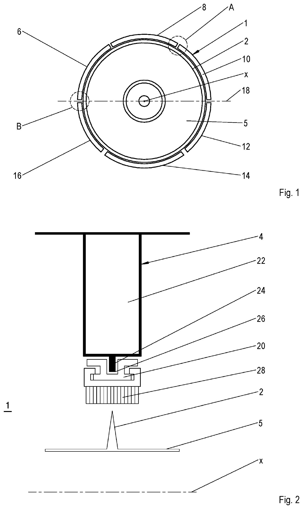
[0027]A positioning of a seal carrier 1 according to the invention relative to sealing fins 2 in a turbomachine, for example, an aircraft engine, is shown in greatly simplified manner in FIGS. 1 and 2. The seal carrier 1 forms a part of an adjustable guide vane ring 4, which is disposed on the compressor side in the turbomachine. The sealing fins 2 are disposed on the rotor side and are designed as projections that encircle a rotor 5 rotating around a longitudinal axis x in the turbomachine in the peripheral direction.

[0028]The seal carrier 1 has a ...


PUM


Abstract

The segmented seal carrier of a guide vane ring of a turbomachine has a number of segments that form two half-rings of the seal carrier when assembled. They are clamped together by their opposite-lying, corresponding lateral contact regions.

Description

BACKGROUND OF THE INVENTION[0001]The invention relates to a segmented seal carrier for a turbomachine according to the present invention, an adjustable guide ring, and a turbomachine.[0002]The seal carrier according to the invention is used as follows, for example, in a turbomachine. For establishing optimal operating conditions, turbomachines such as aircraft engines and stationary gas turbines have, on the compressor side, at least one adjustable row of guide vanes having a plurality of guide vanes that can pivot around their vertical axis. The row of guide vanes forms with an inner ring a so-called adjustable guide vane ring. The inner ring serves for the stabilizing or for the radially inner bearing of the guide vanes. An outer bearing of the guide vanes as well as the actuation thereof is carried out via adjusting journals of the guide vanes that interact with a corresponding adjustment means. On or at the inner ring is guided a seal carrier that is provided with sealing elemen...

Claims


Application Information

Patent Timeline
Patent Type & Authority Patents(United States)
IPC IPC(8): F04D29/08F04D27/00F04D29/56
CPCF04D27/002F04D29/563F04D29/083F05D2240/50F05D2220/323F16J15/442F16J15/444F05D2260/36F01D11/001
Inventor JAKIMOV, ANDREASSCHARL, RICHARDSCHLOTHAUER, STEFFEN
Owner MTU AERO ENGINES GMBH
Why Eureka
Try Eureka