UV-irradiation device for treating fluids, comprising an improved cleaning device

a technology of irradiation device and cleaning device, which is applied in the direction of material analysis using wave/particle radiation, instruments, optical means, etc., can solve the problems of device function device operation only to a limited extent, and insufficient cleaning fluid on etc., to achieve effective counteract the formation of deposits, mechanically cleaning the surface of the jacket tube, and effective cleaning

Inactive Publication Date: 2006-09-26
XYLEM IP HLDG +1
View PDF8 Cites 2 Cited by
  • Summary
  • Abstract
  • Description
  • Claims
  • Application Information

AI Technical Summary

Benefits of technology

[0009]Because there is disposed in the chamber at least one ring made of an elastomeric material and having a non-circular cross section, with the inner diameter in the relaxed state being less than or equal to the outer diameter of the jacket tube, the mechanical cleaning of the surface of the jacket tube is intensified and the rolling of the ring over deposits is effectively avoided. The material is urged against the surface with a pre-stress, and is automatically adjusted when wear occurs. This device can effectively counteract the formation of deposits upon the surface of the jacket sleeve and can prevent them, even when there is a high content of lime in the water or wastewater that is to be treated.
[0010]If the material is a fluoro elastomer, for example the material VITON offered by the company DuPont Dow Elastomers, the ring is not only not sensitive to heat, oxidation, ozone effects, and ultraviolet radiation; it is furthermore mechanically very durable.
[0012]If the cleaning elements, in the longitudinal direction of the jacket tube, have support means, especially polymeric or metal discs, that are disposed next to the end faces of the ring, and that counteract a deformation of the ring upon actuation of the cleaning elements, a deflection of the ring relative to the impurities that adhere to the surface is prevented. The cleaning effect is thus improved.

Problems solved by technology

With numerous applications there is a problem that the lamp units of the irradiation devices become dirty from the outside.
In practice, this device functions only to a limited extent since the O-ring seals of the chamber are very sensitive to mechanical damage or deviations in dimensions relative to the surface of the jacket tube, and furthermore the chemical action of the cleaning fluid on the surface of the jacket tube is not sufficient, without mechanical assistance, to prevent the formation of deposits, or to remove such deposits.
For mechanically removable deposits, this device is too expensive.
The O-rings themselves have no significant cleaning effect since on the one hand their circular cross section forms a very acute contact angle with the jacket tube, and on the other hand with strongly adhering or abrasive deposits the O-rings tend to roll over them.
Where the impurities adhere much more strongly, the effect of this cleaning device is limited.

Method used


Image

  • UV-irradiation device for treating fluids, comprising an improved cleaning device
  • UV-irradiation device for treating fluids, comprising an improved cleaning device
  • UV-irradiation device for treating fluids, comprising an improved cleaning device

Examples


Embodiment Construction

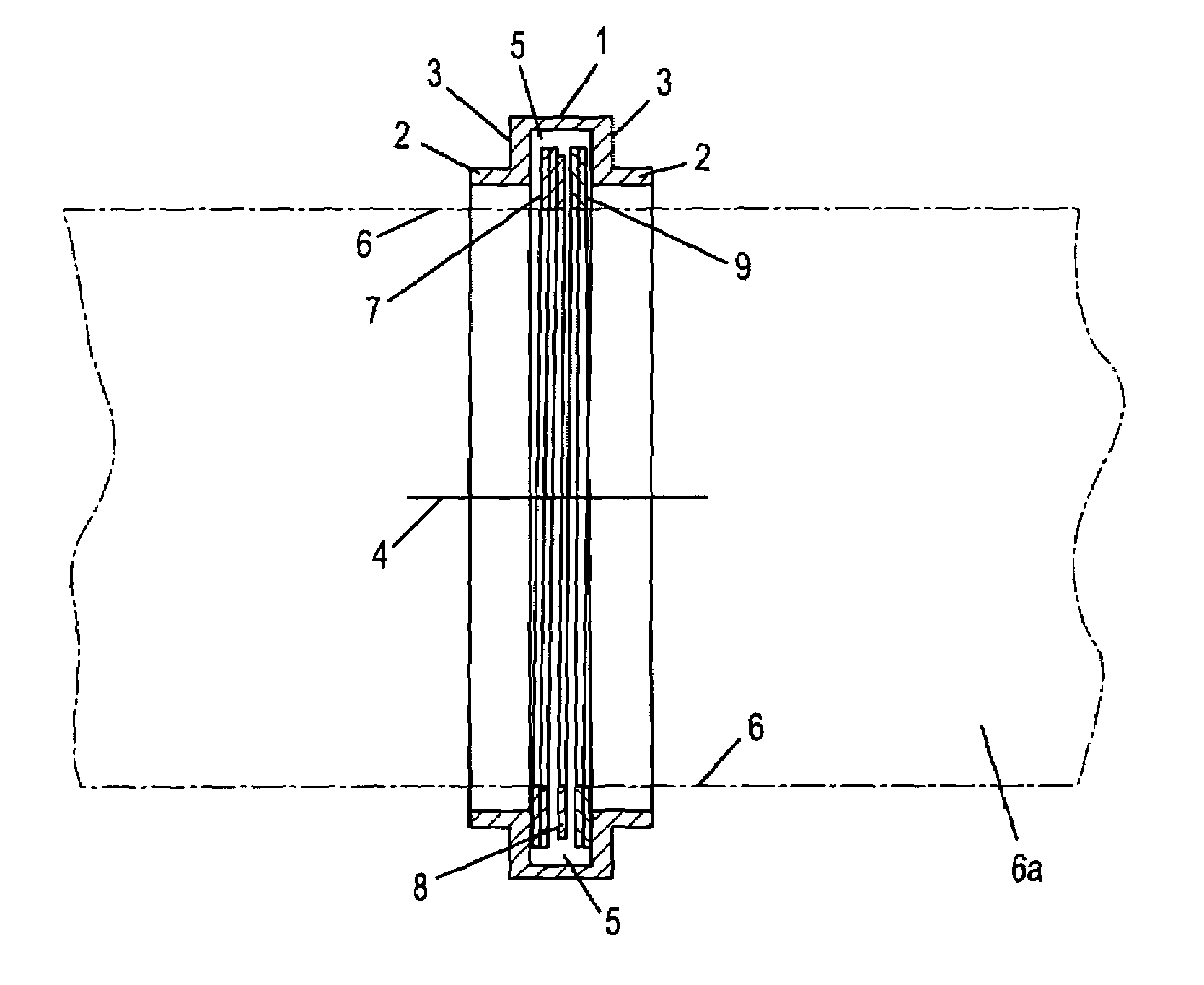
[0023]FIG. 1 shows a view of a cleaning element of an inventive UV irradiation device in the radial direction. The cleaning element is essentially axially symmetrical and has a central portion 1 of greater diameter that is delimited to both sides in the axial direction by a respective guide portion 2 of lesser outer diameter.

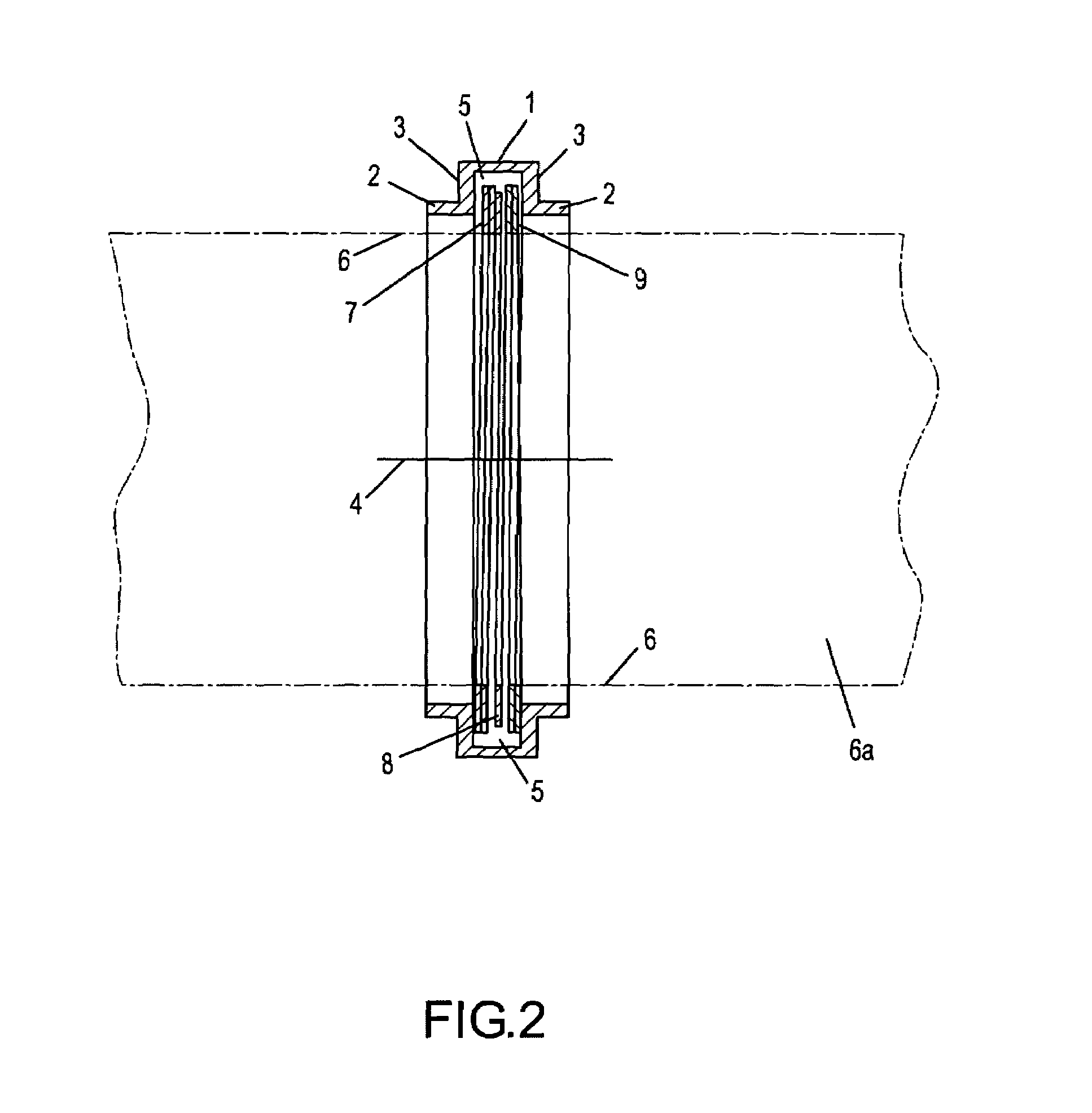
[0024]FIG. 2 is a cross section taken along the line II—II in FIG. 1.

[0025]The guide portions 2 are essentially tubular and are monolithic with the portion 1, whereby radially extending faces 3 form the transition between the guide portions 2 and the portion 1.

[0026]The faces 3 and the peripheral surface of the portion 1 delimit between them a groove or a recess 5 that is open toward an axis 4 and that has a nearly square cross section. The reference numeral 6 indicates the outer surface line of a jacket tube that during operation carries the cleaning element.

[0027]Disposed in turn in the recess 5 is a package comprised of a support element 7, a ring 8 and a fur...


PUM

PropertyMeasurementUnit
thicknessaaaaaaaaaa
thicknessaaaaaaaaaa
radial widthaaaaaaaaaa

Abstract

A UV irradiation device for the treatment of fluids has an improved device for the cleaning of the surfaces of the jacket tube with a number of lamp units that each have a radiation source and a jacket tube that surrounds the radiation source, whereby the lamp units are essentially cylindrical. A cleaning device has cleaning elements that annularly extend around the jacket tubes 3. Each jacket tube has at least one cleaning element, and the cleaning elements are displaceable in the longitudinal direction of the jacket tubes by at least one drive unit. The cleaning elements have an axially delimited, annular chamber that is open towards the surface of the jacket tubes. At least one elastomeric ring is disposed in the chamber.

Description

BACKGROUND OF THE INVENTION[0001]The present invention relates to a UV irradiation device.[0002]Such a device is known from U.S. Pat. No. 5,874,740.[0003]Microbiologically contaminated liquids, such as, for example, waste water from clarification or sewage-treatment plants, are disinfected in a particularly environmentally protective manner by being treated with ultraviolet radiation. For this purpose, various irradiation devices are known in the state of the art. With numerous applications there is a problem that the lamp units of the irradiation devices become dirty from the outside.[0004]In the aforementioned patent a device is therefore proposed according to which annular chambers surround the lamp ends. These chambers rest against the surface of the jacket tubes where they are sealed via two O-rings. The interior of the chambers is filled via a supply unit with a cleaning liquid, for example phosphoric acid. To clean the surface of the lamp unit, the chamber that is filled with...

Claims


Application Information

Patent Timeline
Patent Type & Authority Patents(United States)
IPC IPC(8): B01J19/08B01J19/12B08B1/00C02F1/32
CPCB08B1/008C02F1/325C02F2201/324C02F1/32
Inventor MENKE, GERD
Owner XYLEM IP HLDG
Why Eureka
Try Eureka