Method for operating a wind power plant

a technology for wind power plants and turbines, applied in the direction of engine control parameters, active/predictive/anticipative control, engine control parameters, etc., can solve the problems of aerodynamic problems, negative effect on the life of individual components, and the optimal position of the rotor blade with respect to the wind, so as to reduce the pretension to which the rotor blade is subjected outside the tower pass

Inactive Publication Date: 2011-02-01
DAUBNER & STOMMEL BAU WERK PLANUNG
View PDF23 Cites 2 Cited by
  • Summary
  • Abstract
  • Description
  • Claims
  • Application Information

AI Technical Summary

Benefits of technology

[0013]The characteristics are preferably determined or measured during the operation of the wind power plant, i.e. particularly during the movement of rotation of the rotor, continuously or at certain time intervals. The parameters of the counterforces to be introduced are adjusted in dependence on the values determined or measured. This makes it possible to optimally adapt the counterforces to the forces acting on the component.
[0022]Accordingly, the introduction of the counterforces is controlled by means of the deformation or pretensioning of the component, particularly of the rotor blade, in such a manner that forces to which the component is exposed, for example due to wind load, can be effectively counteracted by a component deformation in the opposite direction.
[0023]In a further embodiment of the present invention, the force introduction into the or each rotor blade can be controlled periodically in such a manner that the pretension to which the rotor blade is subjected outside the tower pass is reduced when the rotor blade, particularly when pointing downwards, is located in the area of the tower pass, i.e. passes over the tower surface. Outside the tower area, the pretension of the rotor blade is then increased again to the respective initial value. Without this periodic reduction in the pretension in the tower area, there would be a risk that the pretension is greater than necessary due to the low wind load in the tower pass. Without reduction in pretension, the rotor blade would possibly move out of the usual plane of rotation into the area facing the wind during the tower pass which can lead to loading on the rotor blade and to aerodynamically unfavourable conditions.

Problems solved by technology

These actions of force, in turn, lead to different problems.
When wind velocities deviate from this, the position of the rotor blade with respect to the wind is not optimal, therefore.
The forces influencing the individual components of the wind power plant such as, for example, the wind load, the respective inherent weight of the components or the like do not only lead to aerodynamic problems.
In addition, these forces, particularly cyclic loads, also have a negative effect on the life of the individual components.
The disadvantageous factor in this solution is, however, that naturally, it is not possible to prevent a multiplicity of forces acting on the rotor blade and having a negative influence on being produced.

Method used


Image

  • Method for operating a wind power plant
  • Method for operating a wind power plant
  • Method for operating a wind power plant

Examples


Embodiment Construction

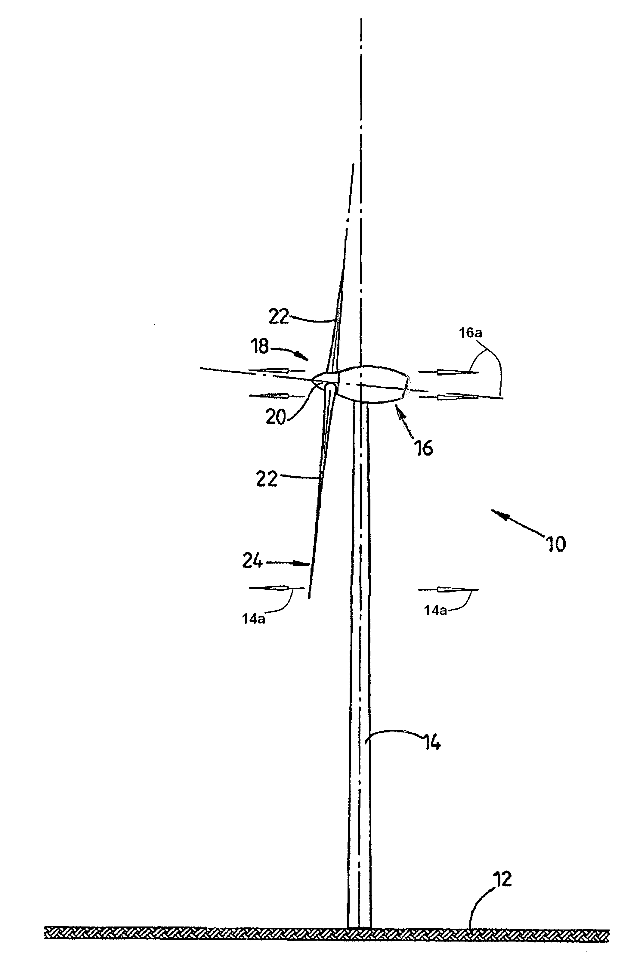
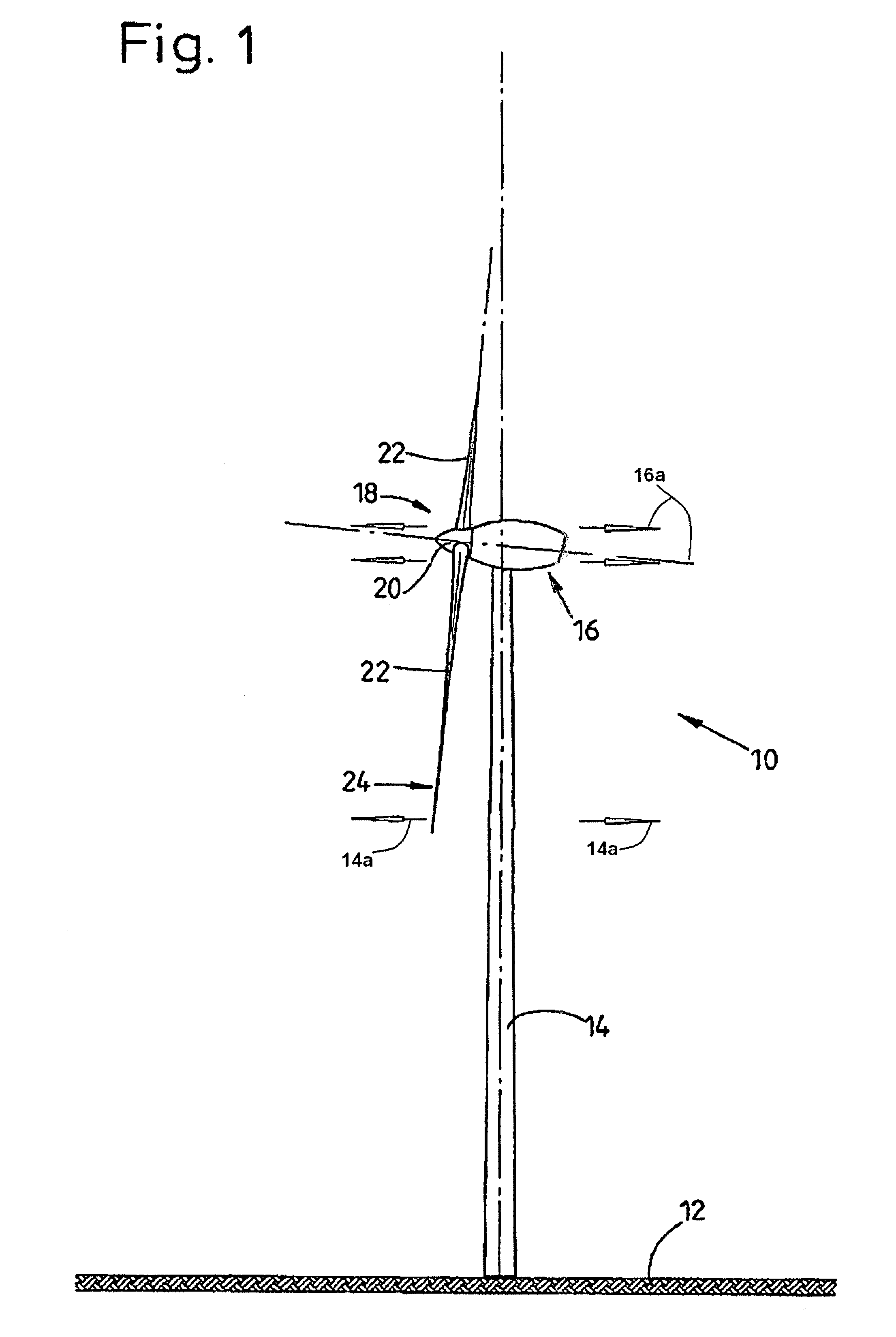
[0037]FIG. 1 shows a wind power plant 10 which has at the top end of a vertical tower 14 arranged on a horizontal underground 12 a nacelle 16 arranged on the tower top. As is known to those of skill in the prior art, many types of embodiments are conceivable for the precise arrangement of a tower of a wind power plant. Naturally, the invention is not restricted to the truncated cone-shaped form of the tower 14 described in the drawing.

[0038]At one end of the nacelle 16 facing the wind, a rotor 18 is arranged which has a hub 20. Three rotor blades 22 are connected to the hub 20, the rotor blade roots of the rotor blades 22 being inserted into corresponding openings in the hub 20 and connected to the latter in familiar manner.

[0039]The rotor 18 rotates about an axis slightly inclined to the top with respect to the horizontal. As soon as wind impinges on the rotor blades 22, the rotor 18 and its rotor blades 22 are placed into rotation about the rotor shaft. The movement of the rotor s...


PUM


Abstract

A method for operating a wind power plant, in which the wind power plant (10) has a multiplicity of components, but at least one rotor (18) with at least one rotor blade (22) and a generator for converting the mechanical energy of the rotor (18) into electrical energy and possibly a tower (14) on which the rotor (18) is arranged. Counterforces which counteract forces acting on the component (22), particularly wind loads, can be introduced into at least one component during the movement of rotation of the rotary blade (22).

Description

STATEMENT OF RELATED APPLICATIONS[0001]This patent application is based on and claims convention priority on German Patent Application No. 10 2006 020 257.0 having a filing date of 27 Apr. 2006, which is incorporated herein in its entirety by this reference.BACKGROUND OF THE INVENTION[0002]1. Technical Field[0003]The present invention relates to a method for operating a wind power plant, wherein the wind power plant has a multiplicity of components but at least one rotor having at least one rotor blade and a generator for converting the mechanical energy of the rotor into electrical energy, wherein one or more characteristics are determined, particularly measured, which are directly or indirectly dependent on forces acting on the component and / or conversely depend on these forces acting on the component such as, for instance, the current wind speed or an operating parameter of the wind power plant, for instance the wind angle of attack of the rotor blade. The present invention also ...

Claims


Application Information

Patent Timeline
Patent Type & Authority Patents(United States)
IPC IPC(8): B63H1/06
CPCF03D1/0675F03D7/0296F05B2220/709F05B2260/96F05B2270/32F05B2270/321F05B2270/322F05B2270/404Y02E10/721Y02E10/723Y02E10/72
Inventor STOMMEL, MATTHIAS
Owner DAUBNER & STOMMEL BAU WERK PLANUNG
Why Eureka
Try Eureka