Imaging device for the stabilized imaging of an object onto a detector

a technology of imaging device and detector, which is applied in the field of imaging device for the stabilized imaging of an object onto a detector, can solve the problems of unsharp recording of objects, and achieve the effects of reducing scattered light loss

Inactive Publication Date: 2010-08-31
BODENSEEWERK GERATETECHNIK GMBH
View PDF10 Cites 2 Cited by
  • Summary
  • Abstract
  • Description
  • Claims
  • Application Information

AI Technical Summary

Benefits of technology

[0014]In a further refinement of the invention, the control unit is provided for calculating an operating point of the optical element outside the intermediate image plane. It is possible to counteract a wobbling movement of the imaging of the object over the detector particularly effectively and with low scattered-light losses. As the shift-out of the optical element increases, the scattered-light losses increase, as a result of which the efficiency of the imaging device decreases. A good operating point for executing the displacement movements therefore depends, inter alia, on the extent of the wobbling movement, the speed of the wobbling movement, the brightness of the imaging and the desired image sharpness and intensity. A favourable operating point can be calculated from one or a plurality of these factors.
[0015]The control unit is advantageously provided for calculating an operating point from the extent of a wobbling movement of the imaging over the detector. Extensive stabilization of the imaging onto the detector can be achieved in conjunction with a high efficiency, that is to say low scattered-light losses. In this case, the extent of the wobbling movement may be the average magnitude of the wobbling movement over a predetermined time period. The greater this average wobbling movement, determined as length, the further away the operating point expediently is from the intermediate image plane, in order to achieve a maximum stabilization of the imaging with the aid of a displacement of the micro-optical lens array. The extent of the wobbling movement may also be the average or maximum speed of the movement of the imaging over the detector over a predetermined time period. In order to compensate for a rapid movement of the imaging, the micro-optical lens array must perform a large displacement per unit time. If necessary, this displacement can be reduced by correction of the operating point, for example by arranging it further away from the intermediate image plane.
[0016]A rapid stabilization movement of the micro-optical lens array can be achieved if the control unit is provided for controlling movement of the optical element into the operating point.
[0017]High-quality images of the imaging device can be achieved if the control unit is provided for including a brightness of the imaging in the calculation of the operating point. In the case of relatively dark imagings, a high scattered-light loss has more serious effects on the quality of the detected imaging than in the case of a very bright imaging. Therefore, in the case of a dark imaging, a scattered-light loss is, if appropriate, to be rated higher than an imaging that is not entirely free of wobbling. Taking account of the brightness of the image may therefore lead to a—seen in relative terms—high image quality.
[0018]The object directed at the method is achieved by means of a method for stabilizing an imaging of an object that is imaged onto a detector, in which an optical element arranged in an imaging beam path between a first and a second optical unit is caused to effect a first stabilization movement for stabilizing the imaging, in which case, according to the invention, a micro-optical lens array is moved as the optical element for the purpose of stabilization. In the case of a micro-optical lens array, a considerable deflection of the beam path, for example of 15°, can be achieved by a slight movement of the micro-optical lens array, for example in the region of a few μm. This makes it possible to track the beam path to a wobbling-dictated movement of the imaging over the detector at very high speed and with a very small energy requirement.
[0019]The optical element is advantageously caused to effect a first stabilization movement for stabilizing the imaging with the aid of an electronic control unit.

Problems solved by technology

The movement of an imaging of a focused object to an undesirable extent over a detector of the camera system leads to an unsharp recording of the object.
This problem exists particularly in a camera system that is guided in a moving machine that is exposed to tremor or carries out a large intrinsic movement, such as, for example, an aeroplane in turbulence or the like.

Method used


Image

  • Imaging device for the stabilized imaging of an object onto a detector
  • Imaging device for the stabilized imaging of an object onto a detector
  • Imaging device for the stabilized imaging of an object onto a detector

Examples


Embodiment Construction

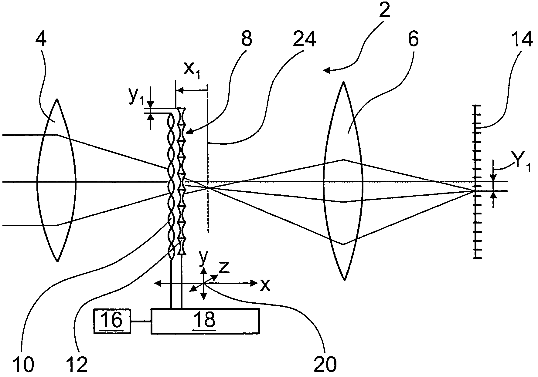
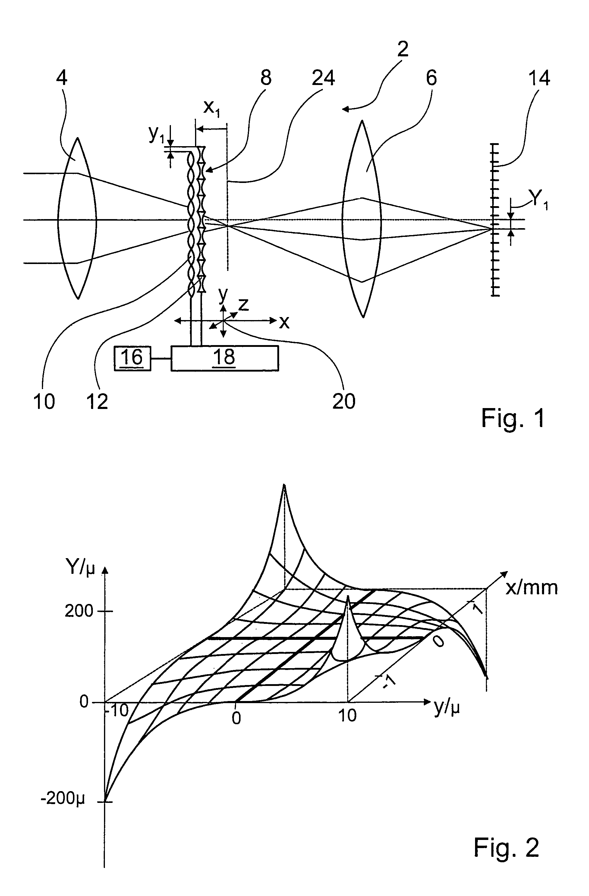
[0027]FIG. 1 shows a highly schematic illustration of an imaging device 2 comprising a first optical unit 4, which is illustrated diagrammatically as a lens, and a second optical unit 6, which is likewise illustrated only diagrammatically as a lens for the sake of clarity. A third optical unit 8 is arranged between the first optical unit 4 and the second optical unit 6 and has an optical element configured as a first micro-optical lens array 10 and a second micro-optical lens array 12. The micro-optical lens arrays 10, 12 each comprise 256×256 lenses formed as converging lenses in the first lens array 10 and as diverging lenses in the second lens array 12. Each lens of the first lens array 10 is assigned to a lens of the second lens array 12. Moreover, the imaging device 2 comprises a detector, 14 having 256×256 detector cells, the boundaries of which relative to one another are indicated using horizontal lines in FIG. 1. Each detector cell is provided for taking up an image pixel. ...


PUM


Abstract

An imaging device (2) for the stabilized imaging of an object onto a detector (14) with a first optical unit (4) and a second optical unit (6) and an optical element that is arranged between the optical units (4, 6) and can be moved for the purpose of stabilizing the imaging on the detector (14). For image stabilization in order to compensate for an undesirable wobbling movement of the imaging over the detector (14), the optical element is constituted of a micro-optical lens array (10).

Description

BACKGROUND OF THE INVENTION[0001]1. Field of the Invention[0002]The invention is based on an imaging device for the stabilized imaging of an object onto a detector with a first and a second optical unit and an optical element that is arranged between the first and second optical units and can be moved for the purpose of stabilizing the imaging on the detector.[0003]A camera system having a high resolution is particularly sensitive to wobbling of the recorded images. The movement of an imaging of a focused object to an undesirable extent over a detector of the camera system leads to an unsharp recording of the object. This problem exists particularly in a camera system that is guided in a moving machine that is exposed to tremor or carries out a large intrinsic movement, such as, for example, an aeroplane in turbulence or the like.[0004]2. Discussion of the Prior Art[0005]EP 0 783 121 A2 discloses an imaging device with a first and a second optical unit and an optical element that is...

Claims


Application Information

Patent Timeline
Patent Type & Authority Patents(United States)
IPC IPC(8): H04N5/228G02B26/08G02B27/64G03B5/00H04N1/03H04N1/193H04N5/232
CPCG02B27/648H04N1/03H04N1/193H04N2201/02491H04N2201/02493H04N2201/046
Inventor THOLL, HANS DIETERKROGMANN, DIRK
Owner BODENSEEWERK GERATETECHNIK GMBH
Why Eureka
Try Eureka