Enhanced privacy switchable backlight system

a backlight system and switchable technology, applied in the field of can solve the problems of low light efficiency, inconvenient operation, and inability to meet the stringent requirements of automotive applications, and achieve the effects of enhanced light efficiency, enhanced switchable privacy display system, and enhanced light efficiency

Active Publication Date: 2021-05-11
SHARP KK
View PDF13 Cites 5 Cited by
  • Summary
  • Abstract
  • Description
  • Claims
  • Application Information

AI Technical Summary

Benefits of technology

[0008]There is a need in the art, therefore, for an enhanced switchable privacy display system by which a strong private mode is achieved, and additionally enhanced light efficiency is transmitted by the privacy optic so that in both the private mode and the public mode, the display system does not appear too dim. The present invention pertains to such an enhanced switchable privacy display system. Such a display system is suitable for automotive displays in which such a strong private mode is required, although principles of the present invention may be applied to any suitable switchable privacy display system. To provide such an enhanced switchable privacy display system, the present invention employs a switchable dual backlight unit system in combination with an additional privacy optic that is positioned on the non-viewing side of the public mode backlight unit and between the private mode backlight unit and the public mode backlight unit.
[0009]A switchable privacy display system has an enhanced dual backlight system that includes a first or privacy backlight unit, a second or public backlight unit, and a privacy optic component situated in between the first and second backlight units, i.e., on a viewing side of the privacy backlight unit and on a non-viewing side of the public backlight unit. Light emitted from the first backlight unit may pass through the second backlight unit. For a display system with a strong privacy mode, the first backlight unit may have a narrower viewing angle range as compared to the second backlight unit. The backlight system may be operated in at least three different modes. In a first or private mode, the first (privacy) backlight unit is on, and the second (public) backlight unit is off. In the private mode, the privacy backlight unit emits light that is predominantly in a narrow viewing angle range, and the off-axis light further is attenuated and substantially eliminated by the privacy optic, so as to provide a strong private mode. In a second or public mode, the first (privacy) backlight unit is off, and the second (public) backlight unit is on. In the public mode, the privacy backlight unit may not emit light, and the public backlight unit emits light to illuminate the image panel in a wide viewing angle range for a strong public mode. In exemplar embodiments, both backlight units may be on to achieve a public mode of any desired or enhanced brightness.

Problems solved by technology

The main obstacle preventing this from becoming a reality is privacy: by law in many jurisdictions and otherwise for general safety concerns, a driver must not be able to view moving image content on a display while driving.
Accordingly, the conventional configuration of FIG. 1A results in a privacy mode that in particular does not meet the stringent requirements for automotive applications.
One drawback of this system, however, is that the light efficiency is low and the public mode can appear dim because a Louvre film generally has a low light efficiency, transmitting only about 35% of the light from a backlight.
When the HHAN cell is placed in the scattering mode, the already low level of collimated light is scattered out to wider angles, which can result in a dim public mode.
Comparably as with other conventional configurations, the switchable dual backlight system 10a of FIG. 2 does not have a sufficiently strong privacy mode to be used in automotive applications.
One downside to the switchable dual backlight system with an additional privacy optic solution such as the privacy LCD 22a / 22b is that the privacy optic also acts on the light emitted from the public mode backlight unit 12b, which reduces the brightness and performance of the public mode.

Method used


Image

  • Enhanced privacy switchable backlight system
  • Enhanced privacy switchable backlight system
  • Enhanced privacy switchable backlight system

Examples


Embodiment Construction

[0038]Embodiments of the present invention will now be described with reference to the drawings, wherein like reference numerals are used to refer to like elements throughout. It will be understood that the figures are not necessarily to scale.

Switchable Privacy Backlight and Display System Overview

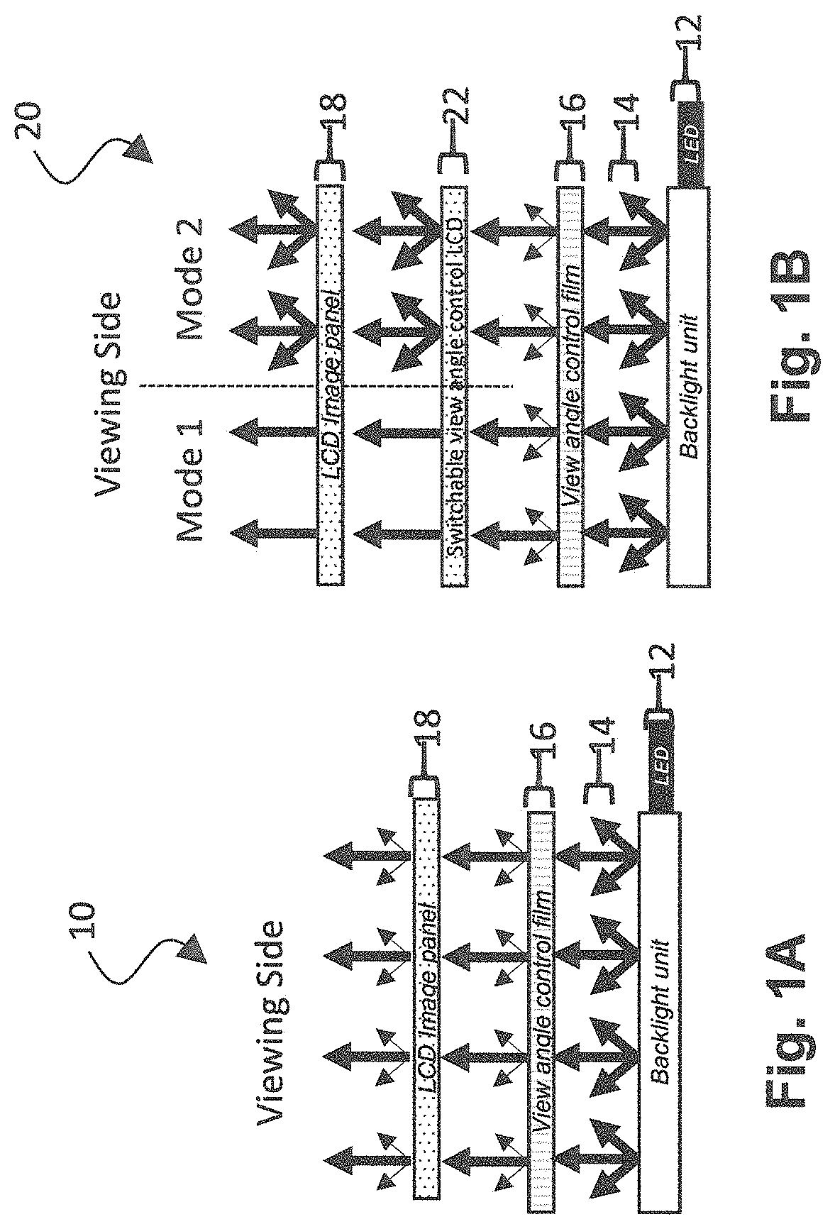
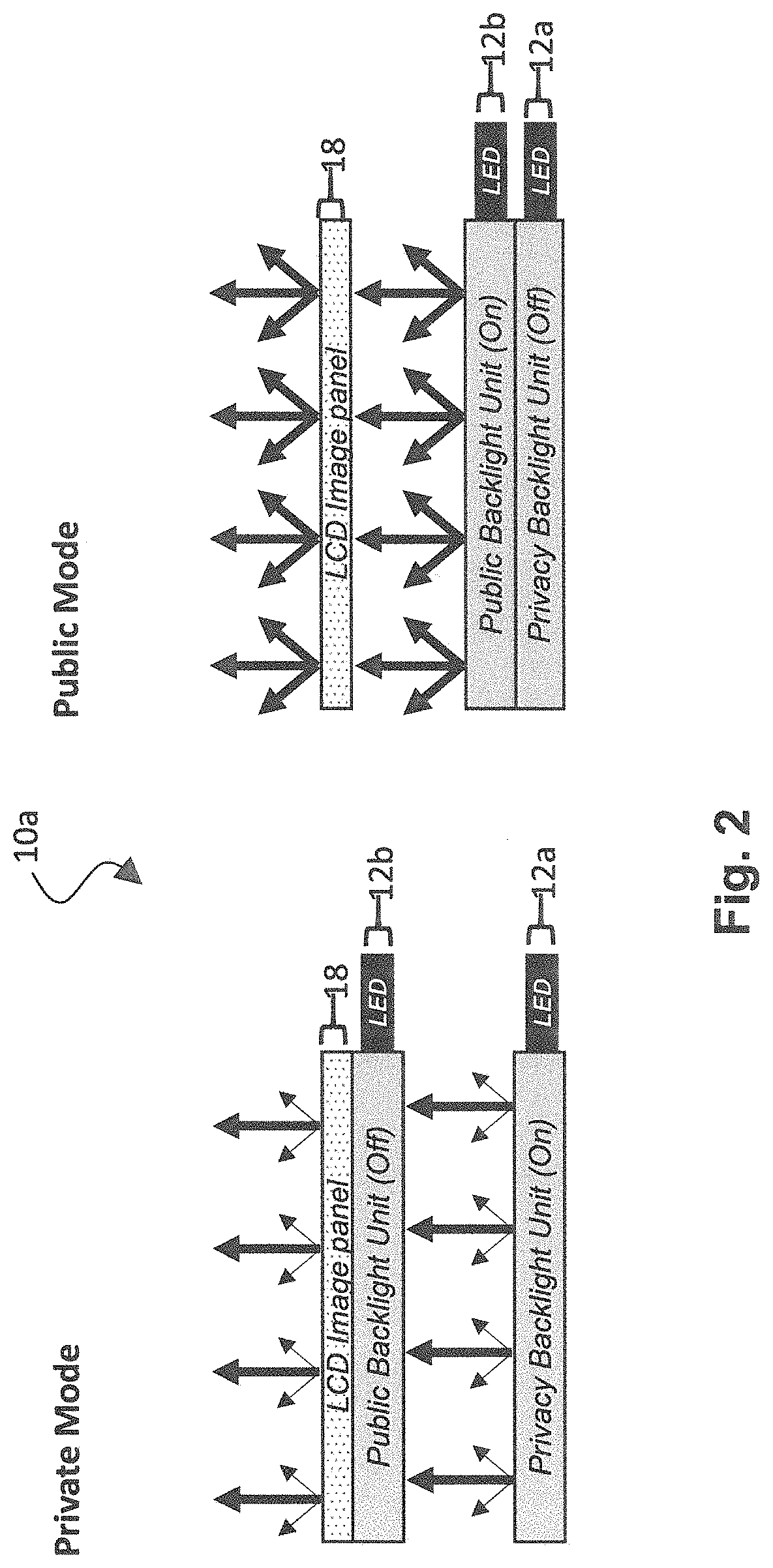
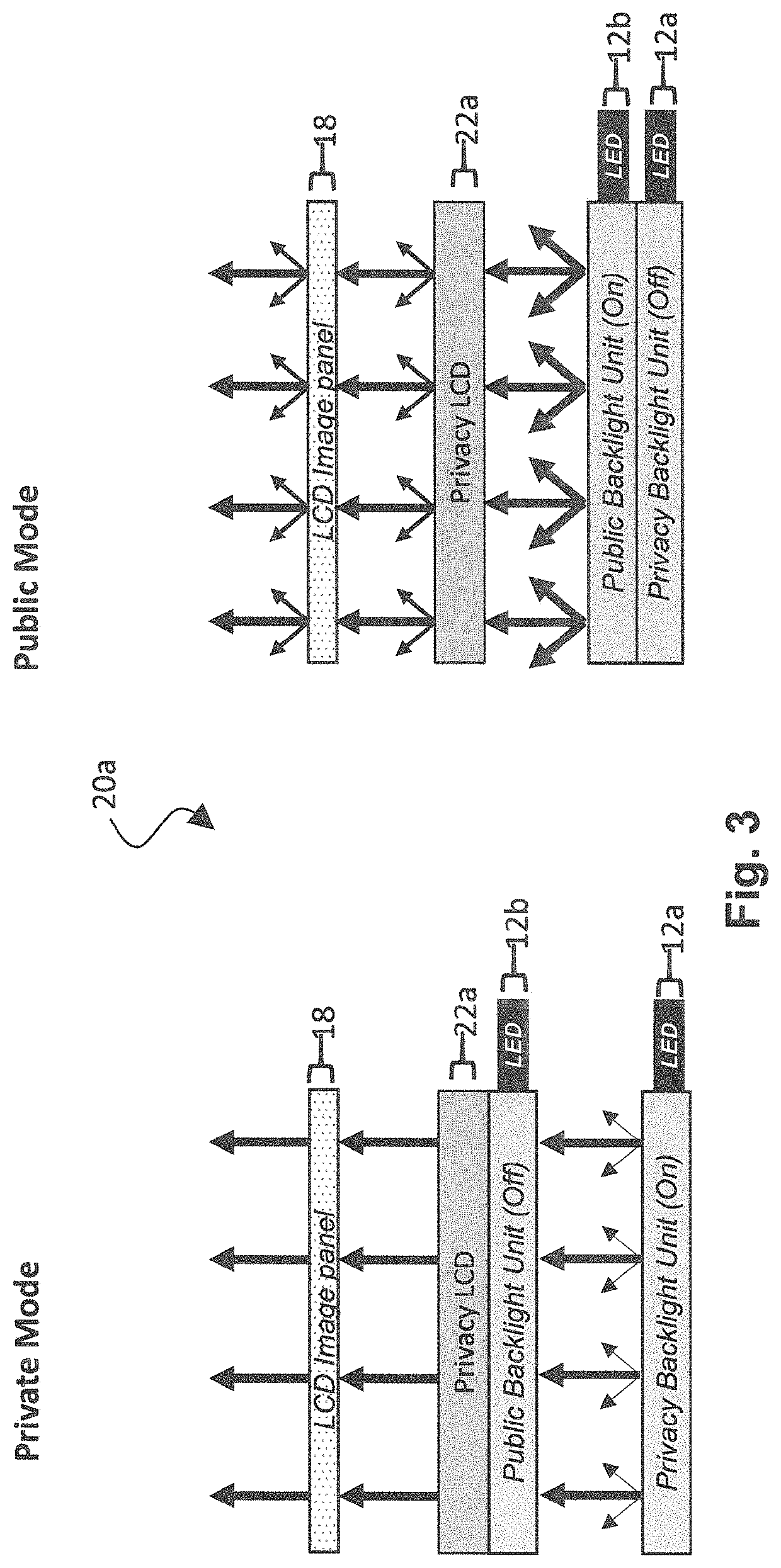
[0039]The present invention pertains to an enhanced switchable privacy display system by which a strong private mode is achieved, and additionally enhanced light efficiency is transmitted by the privacy optic so that in both the private mode and the public mode, the display system does not appear too dim. Such a display system is suitable for automotive displays in which such a strong private mode is required, although principles of the present invention may be applied to any suitable switchable privacy display system. To provide such an enhanced switchable privacy display system, the present invention employs a switchable dual backlight unit system in combination with an additional priva...


PUM

PropertyMeasurementUnit
thicknessaaaaaaaaaa
thicknessaaaaaaaaaa
viewing anglesaaaaaaaaaa

Abstract

A backlight system controls a viewing angle in a switchable privacy display system that achieves a strong private mode and enhanced brightness in the private and public modes as compared to conventional configurations. The backlight system includes a first backlight unit that emits light from a non-viewing side of the backlight system toward a viewing side of the backlight system; a second backlight unit located on a viewing side of the first backlight unit that emits light toward the viewing side of the backlight system; and a privacy optic that includes a liquid crystal material and is located on a non-viewing side of the second backlight unit and between the first backlight unit and the second backlight unit, wherein the privacy optic operates to transmit light from the first backlight unit in a limited viewing angle range.

Description

TECHNICAL FIELD[0001]The present invention relates to a switchable privacy display system for use, for example, as an automotive display involving a backlight system that is switchable between a strong privacy mode and a bright public mode.BACKGROUND ART[0002]Displays in automotive vehicles are becoming more and more prominent. There is a push for larger displays to become a common feature in cars including entertainment displays for the passenger. The main obstacle preventing this from becoming a reality is privacy: by law in many jurisdictions and otherwise for general safety concerns, a driver must not be able to view moving image content on a display while driving. Accordingly, if a passenger is watching video content on the dashboard display, no light (or no variation of light level) is to be visible from the driver's position. Such result necessitates a strong privacy display, by which image content is visible only from within a specific and limited viewing angle range, and ot...

Claims


Application Information

Patent Timeline
Patent Type & Authority Patents(United States)
IPC IPC(8): G02F1/13G02F1/13357F21V8/00G09G3/34G02F1/1335
CPCG02F1/1323G02B6/0031G02B6/0041G02B6/0076G02F1/133602G09G3/3426G02F1/133626G02F2203/62G09G2320/068G02B6/0053G02F1/13476G09G2358/00
Inventor HOPKIN, HYWELSMITH, NATHAN JAMES
Owner SHARP KK
Why Eureka
Try Eureka