
Drain catch

a technology of drain catch and catch rod, which is applied in the field of drain catch, can solve the problems of spilling mess, affecting the safety of workers,

Active Publication Date: 2021-06-15
WRIGHT BRUCE +1
View PDF20 Cites 0 Cited by
  • Summary
  • Abstract
  • Description
  • Claims
  • Application Information

AI Technical Summary

Benefits of technology

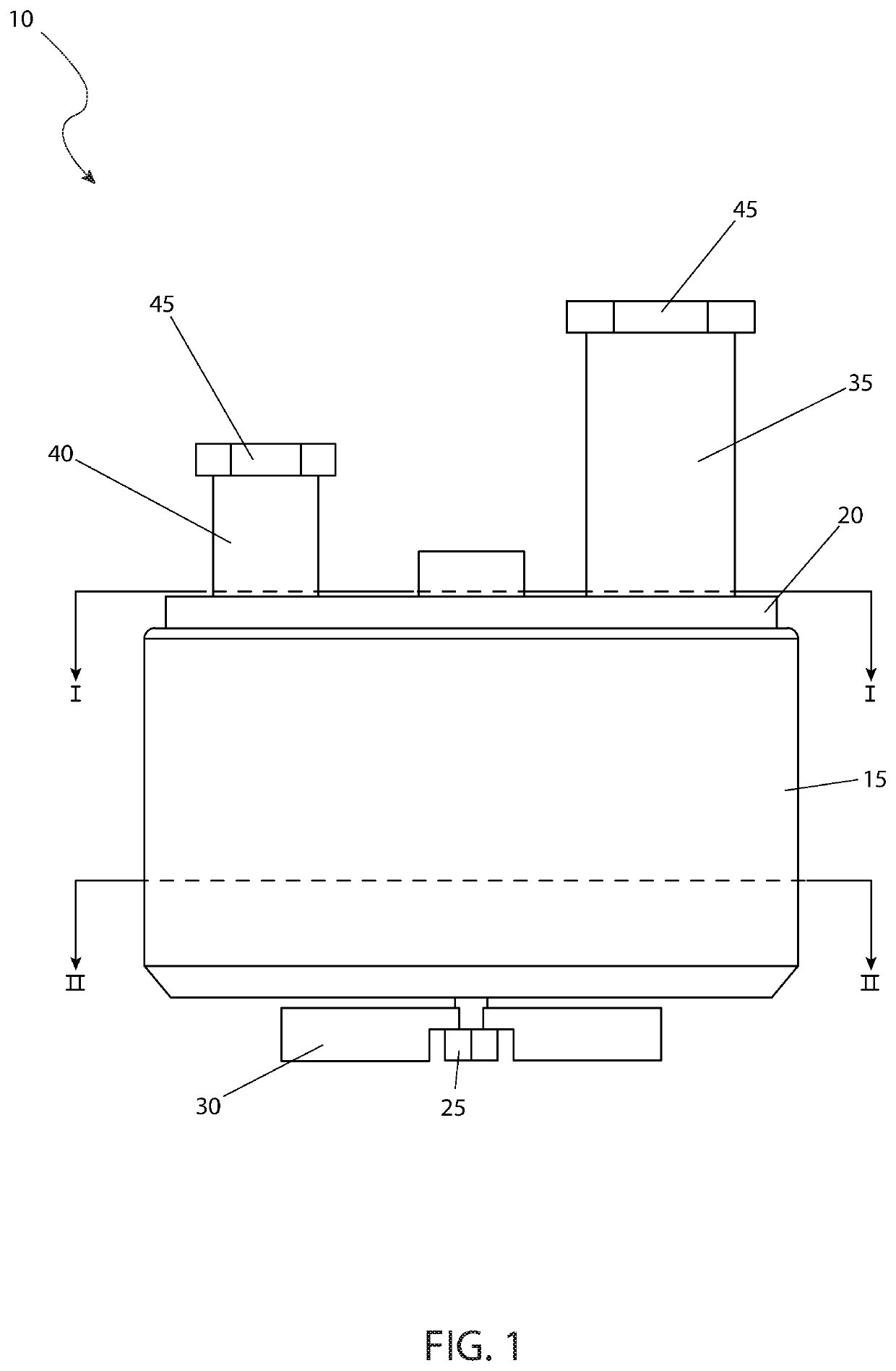
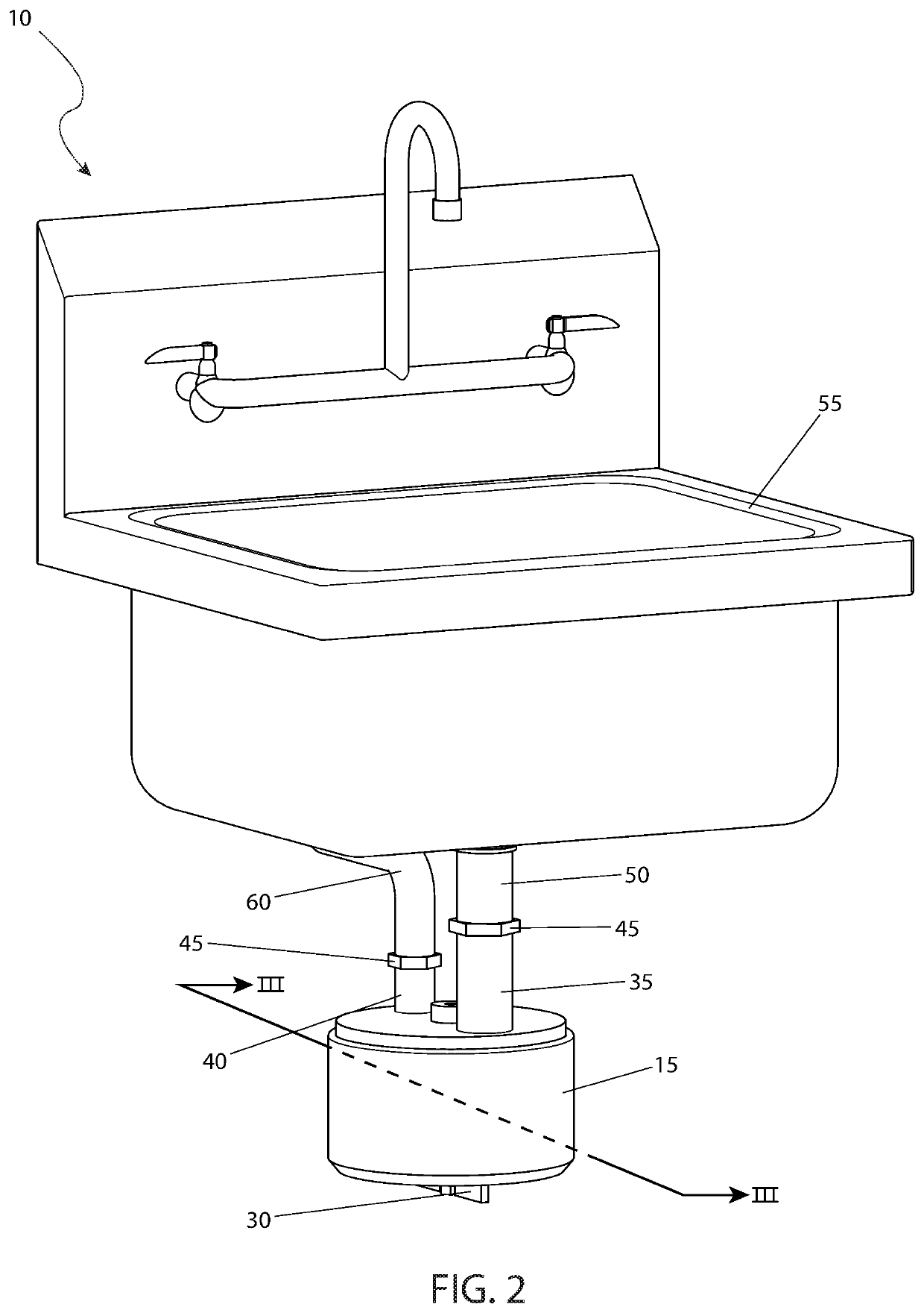
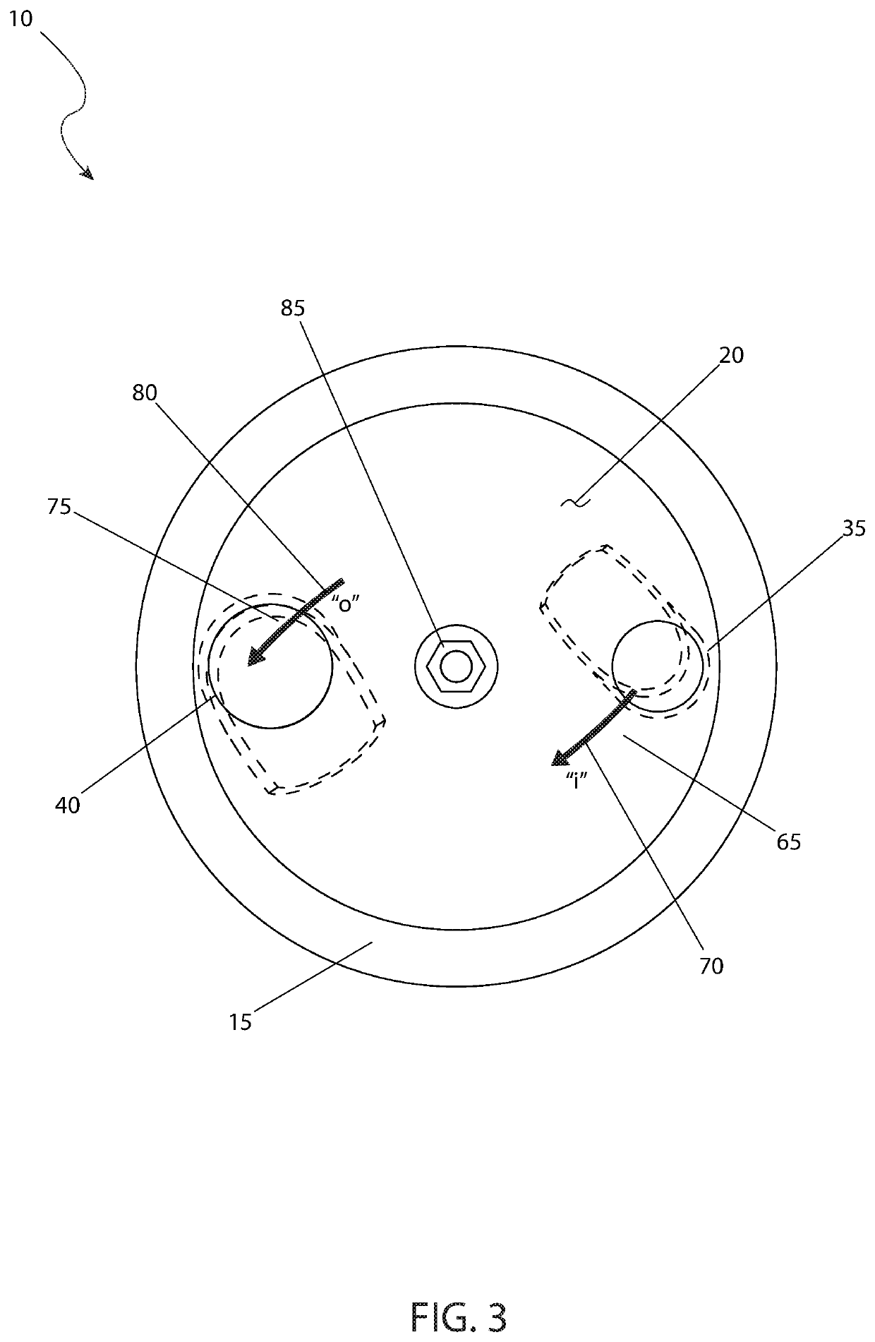
The patent describes a sink drain capture device that can be installed in new construction or retrofits. The device includes a main cup body that is secured to a top plate and has an internal holding bolt that can be easily removed and replaced. The device has an inlet connection and an outlet connection that are connected with a drain outlet using a standard P-trap. The device also has an intake shroud to control wastewater flow and an outtake shroud to control wastewater flow. The device is made of acid resistant polymer and has a water-tight seal between the main cup body and the top plate. The holding bolt can be easily tightened and loosened by a handle, and the device has a simple design that makes it easy to install and replace.

Problems solved by technology

One of life's common problems that most of us have experienced is that of a dropped item down a sink drain.
Any small object can fall down a sink drain, thus causing grief for all involved.
While the object is usually retrieved from the J or P trap below the sink, it is a worrisome and messy job to find out.
Next the trap is slid off, but of course it is filled with water which usually causes a spill and mess even if a bucket is used.
This procedure must be performed every time an object is dropped down the drain, thus causing wear and tear on the rest of the plumbing system as well.
Should one be performing jewelry work such as when sizing, creating, or resetting diamonds or other precious stones, or even working with precious metals, the task is made more complicated by the small size of the object, which in some cases can wash through the trap.

Method used


Image

  • Drain catch
  • Drain catch
  • Drain catch

Examples


Embodiment Construction

[0039]The best mode for carrying out the invention is presented in terms of its preferred embodiment, herein depicted within FIGS. 1 through 5. However, the invention is not limited to the described embodiment, and a person skilled in the art will appreciate that many other embodiments of the invention are possible without deviating from the basic concept of the invention and that any such work around will also fall under scope of this invention. It is envisioned that other styles and configurations of the present invention can be easily incorporated into the teachings of the present invention, and only one (1) particular configuration shall be shown and described for purposes of clarity and disclosure and not by way of limitation of scope. All of the implementations described below are exemplary implementations provided to enable persons skilled in the art to make or use the embodiments of the disclosure and are not intended to limit the scope of the disclosure, which is defined by...


PUM


Abstract

A drain catch has a cylindrical body having a lid and gasket. Secured within the body is a mesh tray. The body also includes a water inlet aperture and a water outlet aperture and is configured to secure about the trap of a sink drainpipe.

Description

RELATED APPLICATIONS[0001]None.FIELD OF THE INVENTION[0002]The present invention relates generally to a drain catch and more specifically for a drain catch for a jeweler.BACKGROUND OF THE INVENTION[0003]One of life's common problems that most of us have experienced is that of a dropped item down a sink drain. Any small object can fall down a sink drain, thus causing grief for all involved. While the object is usually retrieved from the J or P trap below the sink, it is a worrisome and messy job to find out. First the pipe trap must be loosened by removing two large retaining nuts, which requires the use of tools. Next the trap is slid off, but of course it is filled with water which usually causes a spill and mess even if a bucket is used. Next the object is shaken out of the trap, and the trap reinstalled, and inspected for leaks. This procedure must be performed every time an object is dropped down the drain, thus causing wear and tear on the rest of the plumbing system as well.[0...

Claims


Application Information

Patent Timeline
Patent Type & Authority Patents(United States)
IPC IPC(8): E03C1/264
CPCE03C1/264
Inventor WRIGHT, BRUCEMOFFATT, PATRICK
Owner WRIGHT BRUCE
Learn More