Micro-loss combined mechanical DC circuit breaker and its control method

a combined mechanical and breaker technology, applied in the field of electric equipment, can solve the problems of micro-loss state reduce the number and cost of dc circuit breakers in dc grids, and ensure the safety and stability of dc grids with overhead lines, and achieve the effect of ensuring the safety and stability of dc grids

Active Publication Date: 2021-06-15
TIANJIN UNIV
View PDF7 Cites 0 Cited by
  • Summary
  • Abstract
  • Description
  • Claims
  • Application Information

AI Technical Summary

Benefits of technology

[0012]The objective of the present disclosure is to overcome the shortcomings of the prior art and to provides a DC circuit breaker with features of low cost, micro operating losses and auto-reclosing function. The present disclosure is achieved by the following technical scheme:
[0021]Compared to the prior art, the technical scheme of the present disclosure has the following beneficial effects:
[0022]The DC circuit breaker of the present disclosure could works in micro-loss state during normal state, meaning almost no operating cost; the DC circuit breaker of the present disclosure could interrupt fault current on all incoming or outgoing lines connecting on the same DC bus, meaning the number and cost of DC circuit breaker in DC grid could be reduced significantly; the DC circuit breaker of the present disclosure has auto-reclosing function without producing overcurrent or overvoltage, which could ensure the safety and stability of DC grid with overhead lines.

Problems solved by technology

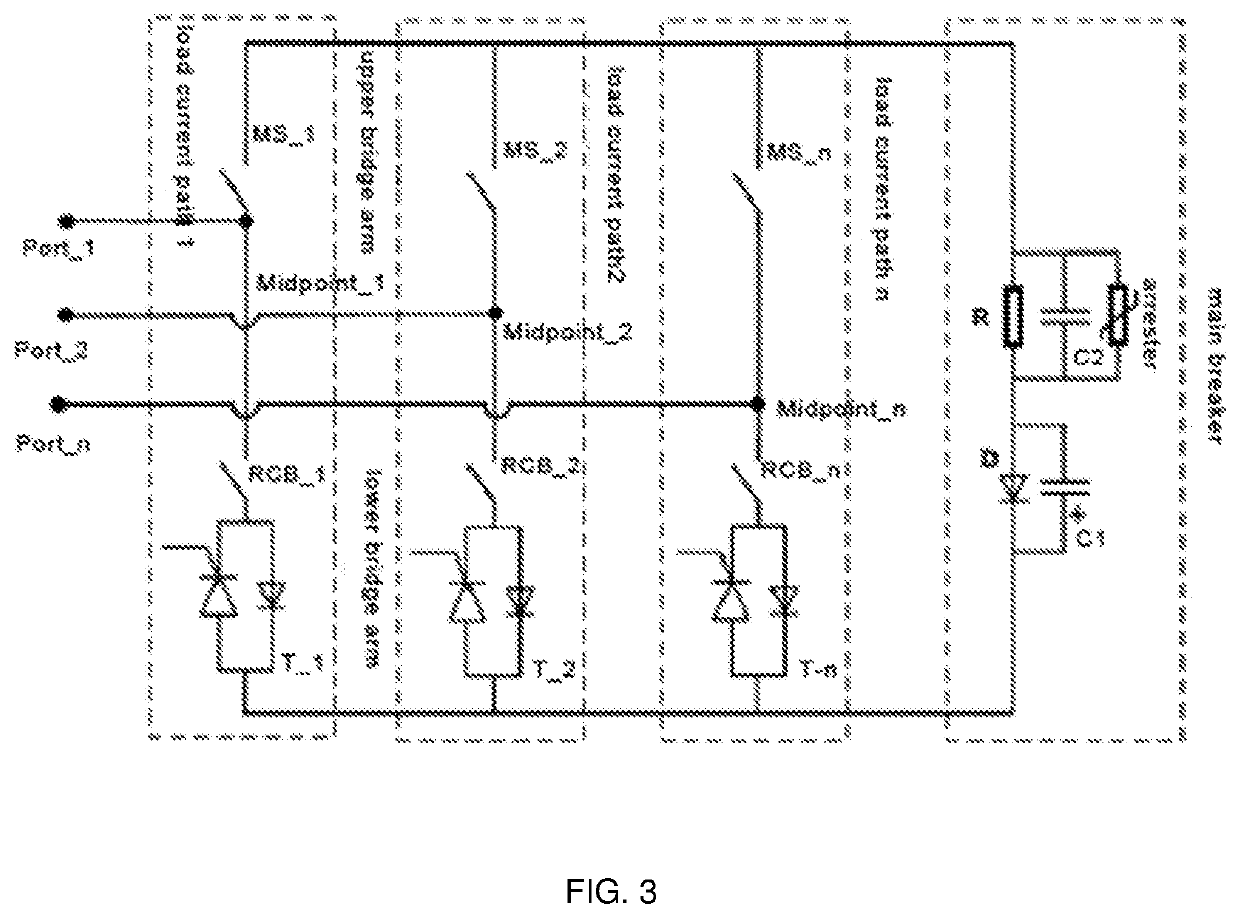
Under this circumstance, the load current only flows through the ultra-fast mechanical switches on the upper bridge arms of all load current paths, resulting in the DC circuit breaker works in micro-loss state.

Method used


Image

  • Micro-loss combined mechanical DC circuit breaker and its control method
  • Micro-loss combined mechanical DC circuit breaker and its control method

Examples


Embodiment Construction

[0027]The technical solution of the present disclosure will be further described below in detail by specific embodiments with reference to the accompanying drawings. The specific embodiments to be described are merely for explaining the present disclosure, rather than limiting the present disclosure.

[0028]FIG. 3 shows a schematic diagram of a detailed embodiment of a micro-loss combined mechanical DC circuit breaker with auto-reclosing function of the present disclosure. As shown in FIG. 3, a micro-loss combined mechanical DC circuit breaker 300 includes n ports (Port_1, Port_2, Port_n), n load current paths (LCP_1, LCP_2, LCP_n) and a main breaker; wherein the load current path (LCP_1, LCP_2, LCP_n) are connected in parallel with the main breaker, each load current path is divided into an upper bridge arm and a lower bridge arm at a connection point (Midpoint_1,Midpoint_2,Midpoint_n), each port (Port_1, Port_2, Port_n) is electrically connected to each connection point (Midpoint_1,...


PUM


Abstract

The present disclosure relates to a micro-loss combined mechanical DC circuit breaker and its control method, consisting n ports, n load current paths and a main breaker; wherein the n load current paths are parallel with the main breaker, and each load current path is divided into an upper bridge arm and a lower bridge arm at a connection point; each port is electrically connected to the connection point of a load current path; the upper bridge arm of each load current path is made of an ultra-fast mechanical switch; the lower bridge arm of each load current path is made of a residual current breaker and a fast closing switch; the main breaker consists of a high-voltage capacitor in series with a low-voltage capacitor that is pre-charged.

Description

CROSS-REFERENCE TO RELATED APPLICATIONS[0001]This application is a bypass continuation application of PCT Application No. PCT / CN2017 / 118163. This application claims priority from PCT Application No. PCT / CN2017 / 118163, filed Dec. 25, 2017, CN Application No. CN 201711237488x filed Nov. 30, 2017 and CN 2017112375079 filed Nov. 30, 2017, the contents of which are incorporated herein in the entirety by reference.[0002]Some references, which may include patents, patent applications, and various publications, are cited and discussed in the description of the present disclosure. The citation and / or discussion of such references is provided merely to clarify the description of the present disclosure and is not an admission that any such reference is “prior art” to the present disclosure described herein. All references cited and discussed in this specification are incorporated herein by reference in their entireties and to the same extent as if each reference was individually incorporated b...

Claims


Application Information

Patent Timeline
Patent Type & Authority Patents(United States)
IPC IPC(8): H02H3/087H01H9/54
CPCH02H3/087H01H9/547H02J1/00H01H9/541H01H33/596H01H2009/543H02H7/125
Inventor WEN, WEIJIELI, BIN
Owner TIANJIN UNIV
Why Eureka
Try Eureka