
Misfire detection device for internal combustion engine, misfire detection system for internal combustion engine, data analyzer, controller for internal combustion engine, method for detecting misfire of internal combustion engine, and reception execution device

a technology for internal combustion engines and execution devices, which is applied in the direction of electric control, machines/engines, fuel injection control, etc., can solve the problems of increasing the number of man-hours for adaptation, increasing the dimension of input variables, and increasing the calculation load of in-vehicle devices. , to achieve the effect of reducing the calculation load of in-vehicle devices

Active Publication Date: 2021-06-29
TOYOTA JIDOSHA KK
View PDF45 Cites 0 Cited by
  • Summary
  • Abstract
  • Description
  • Claims
  • Application Information

AI Technical Summary

Benefits of technology

[0007]In the above configuration, the value of the misfire variable is calculated using data learned by machine learning, and whether a misfire is present is determined based on the calculated value of the misfire variable. This reduces the number of man-hours for adaptation. The rotation waveform variable used as the input to the mapping specified by mapping data learned by machine learning is a variable based on instantaneous speed variables corresponding to discontinuous ones of the rotational angle intervals selected from the continuous rotational angle intervals. This reduces the dimensions of the input variable as compared to a configuration in which the instantaneous speed variable corresponding to all of the continuous rotational angle intervals is used as the input. The rotation waveform variable indicates the difference between the value of the instantaneous speed variable corresponding to the compression top dead center of the target cylinder, which is subject to detection for a misfire, and the value of the instantaneous speed variable corresponding to the compression top dead center of a cylinder other than the target cylinder. In the above configuration, the variable is configured so that the difference is notable in accordance with whether a misfire is present. With the above configuration, while utilizing information needed to determine whether a misfire is present, the load of calculation for the determination of presence of misfire is reduced.
[0009]The instantaneous speed variable difference is the difference between the instantaneous speed variable corresponding to the compression top dead center of the target cylinder, which is subject to detection for whether a misfire is present, and the instantaneous speed variable corresponding to the compression top dead center of a cylinder differing from the target cylinder. The instantaneous speed variable difference varies in accordance with the operating point of the internal combustion engine. The degree of deviation of the instantaneous speed variable difference when a misfire occurs from the instantaneous speed variable difference when a misfire does not occur also varies in accordance with the operating point of the internal combustion engine. Therefore, when a determination value for determining whether a misfire is present is set for an instantaneous speed variable difference, and whether a misfire is present is determined based on a comparison between the instantaneous speed variable difference and the determination value, the determination value needs to be adapted for every operating point. In this regard, in the above configuration, machine learning is executed for a mapping that outputs a value of the misfire variable through a join operation of the rotation waveform variable, the operating point variable, and the parameter learned by machine learning. This allows for learning of a parameter that is common to the operating points differing from each other.
[0013]Various factors may affect a difference in instantaneous speed between two cylinders in which compression top dead centers are consecutively reached. In this regard, in the above configuration, the value of the misfire variable is calculated based on information related to the difference in instantaneous speed between two cylinders in which compression top dead centers are consecutively reached. This minimizes inclusion of information other than whether a misfire is present in the difference in instantaneous speed.
[0017]The rotational behavior of the crankshaft differs between a random misfire and a continuous misfire. When a single mapping is used to determine a random misfire and a continuous misfire with high accuracy, requirements of the mapping are increased. This may complicate the structure of the mapping. In this regard, in the above configuration, mapping data includes random misfire data and continuous misfire data, so that a random misfire and a continuous misfire are determined with high accuracy while simplifying the structure of each mapping.
[0021]In the above configuration, the output value calculation process is executed outside the vehicle, so that the calculation load of the in-vehicle device is reduced.

Problems solved by technology

Hence, the device determines whether an abnormality is present based on only the averaged rotational behavior, and may not always determine whether a misfire is present based on a variable having a high sensitivity to variation in rotational behavior corresponding to presence of a misfire.
This increases the number of man-hours for adaptation.
This increases the dimension of the input variable and increases the calculation load.
This may cause an erroneous determination when whether misfire is present is determined from only the inter-cylinder variables.
A detection error corresponding to the angle of the crankshaft may occur in the value of the instantaneous speed variable.
This may complicate the structure of the mapping.

Method used


Image

  • Misfire detection device for internal combustion engine, misfire detection system for internal combustion engine, data analyzer, controller for internal combustion engine, method for detecting misfire of internal combustion engine, and reception execution device
  • Misfire detection device for internal combustion engine, misfire detection system for internal combustion engine, data analyzer, controller for internal combustion engine, method for detecting misfire of internal combustion engine, and reception execution device
  • Misfire detection device for internal combustion engine, misfire detection system for internal combustion engine, data analyzer, controller for internal combustion engine, method for detecting misfire of internal combustion engine, and reception execution device

Examples


first embodiment

[0037]Hereinafter, a first embodiment related to a misfire detection device for an internal combustion engine will be described with reference to the drawings.

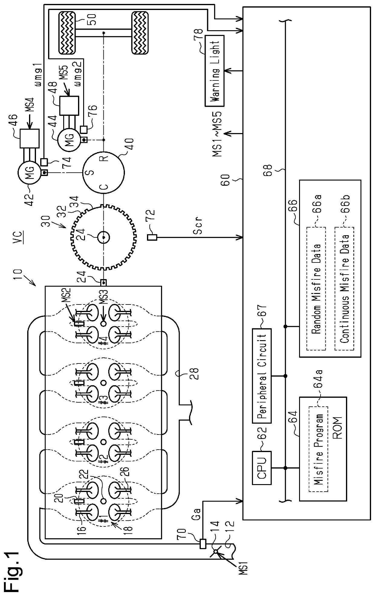
[0038]FIG. 1 shows an internal combustion engine 10 that is mounted on a vehicle VC and includes a throttle valve 14 provided in an intake passage 12. When an intake valve 16 is open, air is drawn from the intake passage 12 into a combustion chamber 18 of each of the cylinders #1 to #4. Fuel is injected into the combustion chamber 18 by a fuel injection valve 20. The air-fuel mixture of air and fuel is subject to combustion when an ignition device 22 produces spark discharge in the combustion chamber 18, and the energy generated by the combustion is output as rotation energy of a crankshaft 24. When an exhaust valve 26 is open, the air-fuel mixture subject to the combustion is discharged to an exhaust passage 28 as exhaust air.

[0039]The crankshaft 24 is coupled to a crank rotor 30 provided with teeth 32 respectively indicating...

second embodiment

[0102]A second embodiment will be described below with reference to the drawings, focusing on the differences from the first embodiment.

[0103]In the present embodiment, the calculation process of the misfire variables PR and PC is executed outside the vehicle.

[0104]FIG. 6 shows a misfire detection system according to the present embodiment. For the sake of convenience, in FIG. 6, members corresponding to the members shown in FIG. 1 are denoted with the same reference characters.

[0105]FIG. 6 shows a controller 60 that is installed in the vehicle VC and includes a communication device 69. The communication device 69 communicates with a center 90 through the network 80 outside the vehicle VC.

[0106]The center 90 analyzes data transmitted from multiple vehicles VC. The center 90 includes a CPU 92, a ROM 94, a storage device 96, a peripheral circuit 97, and a communication device 99, which are configured to communicate with each other through a local network 98.

[0107]FIG. 7 shows the proc...


PUM


Abstract

A misfire detection device for an internal combustion engine includes a storage device and processing circuitry. The storage device stores mapping data. The mapping data is data specifying a mapping that outputs a misfire variable using a rotation waveform variable as an input. The misfire variable is a variable related to a probability that a misfire has occurred in the internal combustion engine. The rotation waveform variable is a variable based on an instantaneous speed variable corresponding to each of discontinuous rotational angle intervals selected from multiple continuous rotational angle intervals.

Description

BACKGROUND1. Field[0001]The following description relates to a misfire detection device for an internal combustion engine, a misfire detection system for an internal combustion engine, a data analyzer, a controller for an internal combustion engine, a method for detecting a misfire of an internal combustion engine, and a reception execution device.2. Description of Related Art[0002]For example, Japanese Laid-Open Patent Publication No. 2009-174397 describes a device that determines whether a misfire is present. Top dead center (TDC) timing refers to timing at which a piston reaches a compression top dead center in a cylinder. A required rotation time refers to a time the crankshaft takes to rotate an angular interval that corresponds to a period from a first TDC timing of a cylinder to a second TDC timing of another cylinder that is adjacent, in terms of time series, to the cylinder. The term “compression top dead center” may refer to a crank angle at which the piston reaches the co...

Claims


Application Information

Patent Timeline
Patent Type & Authority Patents(United States)
IPC IPC(8): F02D41/14F02D41/00F02D41/24
CPCF02D41/1498F02D41/009F02D41/2409
Inventor ANZAWA, TAKUMI
Owner TOYOTA JIDOSHA KK
Learn More