Cable reel trailer

a cable reel and trailer technology, applied in the field of cable reel trailers, can solve the problems that the most dangerous part of the job of the load shifting truck is the one that cannot be moved during the transportation, and achieve the effects of preventing movement during the transportation, facilitating the locking down and facilitating the operation

Active Publication Date: 2021-07-06
WEBER DENNIS +1
View PDF23 Cites 4 Cited by
  • Summary
  • Abstract
  • Description
  • Claims
  • Application Information

AI Technical Summary

Benefits of technology

[0020]My unique cantilever design pulls the weight of the cable reel over the axle. By utilizing a pivot point on a main frame, a 90 degree loading position is made possible. As my main frame pivots and then locks down onto the trailer tongue, once the cable reel has been lifted and brought it into position over the axle, the main frame can be locked down by a cotter pin so that the trailer can be safely transported to a job site. In addition, the cable reel spindle axle can easily be locked down and secured in place to prevent movement during transportation. This means that there is no possibility of a load shift during transportation. As anyone who drives a tractor trailer attached to a trailer knows, load shifting can be the most dangerous part of their job.
[0021]Due to the fact that the present trailer tongue stays fairly level, it is much safer to load a cable reel because the center of gravity is much lower than those shown in the prior art. During the use of my novel cable reel trailer, the operation is much smoother and much safer than prior art inventions as the wheels are stopped and the tractor / trailer being used to pull the main frame into position provides motion that is steady and sure. Upon careful review of the prior art, my design is much simpler, more effective, and safer. One of the true advantages of the present invention is that I have eliminated many components, lowered manufacturing costs, and therefore a cable reel trailer product that is much more economical for buyers.

Problems solved by technology

As anyone who drives a tractor trailer attached to a trailer knows, load shifting can be the most dangerous part of their job.

Method used


Image

  • Cable reel trailer
  • Cable reel trailer
  • Cable reel trailer

Examples


Embodiment Construction

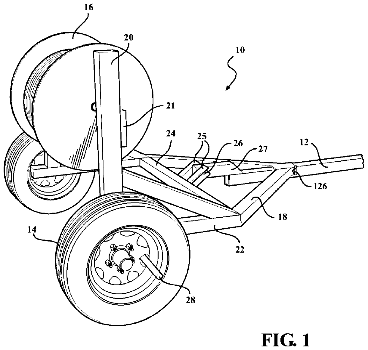
[0035]In accordance with the present invention a new, useful and non-obvious design for a cable reel trailer, a method of making same, and method of using same is disclosed herein. Many of the shortcomings of prior art inventions have been overcome and a cable reel trailer is disclosed that is safer, simpler to manufacture, and is a non-auxiliary powered application. The main frame of my cable reel trailer stays substantially level which is much safer than prior art inventions because the center of gravity is much lower. The cantilever design easily pulls the weight of the cable reel load directly over the axle of the present cable reel trailer. As the tongue of the trailer is attached to a truck, tractor, or some other conventionally available automotive hauling force, solid control over the movement of the cable reel being loaded is achieved. This turns an inherently dangerous operation into one that is much safer, without the use of any additional motive equipment.

[0036]Looking n...


PUM


Abstract

The present invention discloses various aspects of a cable reel trailer that uses the automotive force of a tractor or truck used to transport the trailer, a method of making same, and a method of using. The inclusion of a pivotally connected tongue that is pivotally connected to the main frame of the trailer overcomes many of the aforementioned problems with the prior art because there is no motor or hydraulic system necessary for lifting the cable reel securely on to the trailer. In accordance with the present invention, the towing automotive force, such as a truck, tractor or any other hauling vehicle, provides all the power for lifting the cable reel, rather than requiring a separate power source on the trailer for doing the heavy lifting. By locking up the wheel on the trailer with a wheel stop, the forward movement provided by a towing truck can concentrate on lifting the cable reel instead of moving the trailer forward. This means that no separate on-board power is needed for lifting the cable reel.

Description

REFERENCE TO RELATED APPLICATIONS[0001]This application claims the benefit under 35 U.S.C. 119(e) of U.S. Provisional Application 62 / 364,430 filed on Jul. 20, 2016.STATEMENT REGARDING FEDERALLY SPONSORED RESEARCH OR DEVELOPMENT[0002]Not ApplicableTHE NAMES OF THE PARTIES TO A JOINT RESEARCH AGREEMENT[0003]Not ApplicableINCORPORATION-BY-REFERENCE OF MATERIAL SUBMITTED ON A COMPACT DISC OR AS A TEXT FILE VIA THE OFFICE ELECTRONIC FILING SYSTEM (EFS WEB)[0004]Not ApplicableSTATEMENT REGARDING PRIOR DISCLOSURES BY THE INVENTOR OR A JOINT INVENTOR[0005]Not ApplicableBACKGROUND OF THE INVENTION1. Field of the Invention[0006]The present invention relates to cable reel trailers, methods of manufacturing same, and methods of using same. More particularly, the invention relates to a cable reel trailer that uses an automotive force from a vehicle, whether it be a tractor, a truck or any other type of transport vehicle as the power source to lift the cable reel onto the cable reel trailer.2. De...

Claims


Application Information

Patent Timeline
Patent Type & Authority Patents(United States)
IPC IPC(8): B60P3/035B65H49/38B65H49/32B65H75/42
CPCB60P3/035B65H49/325B65H49/38B65H75/425B65H2701/34
Inventor WEBER, DENNISLEONARDI, SAMUEL M
Owner WEBER DENNIS
Why Eureka
Try Eureka