
Wireless communication system, wireless communication apparatus and directivity determination method

a wireless communication and wireless communication technology, applied in the direction of electrical equipment, transmitter monitoring, transmission monitoring, etc., can solve the problem that the bf of transmission and reception cannot guarantee the satisfactory communication quality of the currently-in-use wireless link, and achieve the effect of suppressing the deterioration of communication quality

Active Publication Date: 2021-07-06
PANASONIC INTELLECTUAL PROPERTY MANAGEMENT CO LTD
View PDF2 Cites 0 Cited by
  • Summary
  • Abstract
  • Description
  • Claims
  • Application Information

AI Technical Summary

Benefits of technology

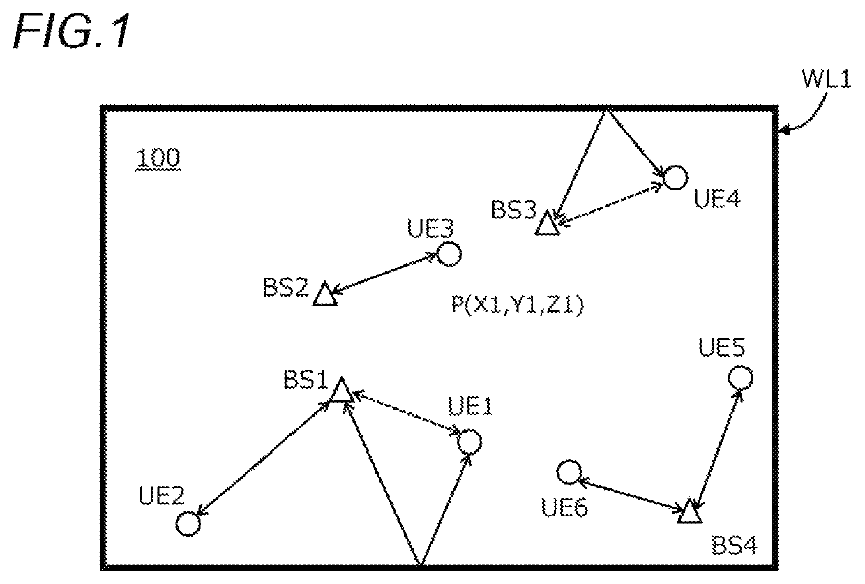
[0014]An object of the present disclosure is to provide a wireless communication system, a wireless communication apparatus and a directivity determination method that, in a case where multiple different wireless links that use the same frequency in a high frequency band are present in the vicinity, are also capable of adaptively determining the directivity relating to transmission and reception on the transmitting side and the receiving side in each of the wireless links, of reducing an influence from any other wireless link to below an allowable, and thus of suppressing a deterioration in communication quality.
[0018]According to the present disclosure, in a case where multiple different links that use the same frequency in a high frequency band are positioned in the vicinity, directivity relating to transmission and reception on the transmitting side and the receiving side in each of the wireless link can be adaptively determined, and an influence of interference from any other wireless link can be reduced to below an allowable level, thereby suppressing a deterioration in communication quality.

Problems solved by technology

However, in a case where multiple wireless links are present with high density in the vicinity and where a wireless link is established using the same frequency as a carrier frequency, such as a frequency of the millimeter wave described above, in some cases, a signal component in any other wireless link is received as an interference component (interference).
For this reason, in the technique in the related art, which involves the first and third steps described above, although the directivity relating to the transmission and reception BF that uses a maximum of a signal component which is received in a currently-in-use wireless link is determined, there is a problem in that the determined directivity relating to the transmission and reception BF cannot necessarily ensure satisfactory communication quality in the currently-in-use wireless link.

Method used


Image

  • Wireless communication system, wireless communication apparatus and directivity determination method
  • Wireless communication system, wireless communication apparatus and directivity determination method
  • Wireless communication system, wireless communication apparatus and directivity determination method

Examples


Embodiment Construction

[0033]A wireless communication system, a wireless communication apparatus and a directivity determination method according to an embodiment, which are disclosed in the present disclosure, will be described in detail below in terms of configuration and operation with appropriate reference to the accompanying drawings. However, in some cases, a description that is more detailed than is necessary is omitted. For example, in some cases, a detailed description of an already-known matter is omitted, or a redundant description of substantially the same configuration is not repeated. The reason for this is to avoid unnecessary redundancy of the following description and to help a person of ordinary skill in the art to achieve easy understanding. It is noted that the accompanying drawings and the following description are provided in order for a person of ordinary skill in the art to get a sufficient understanding of the present disclosure, and therefore that this is not intended to impose a...


PUM


Abstract

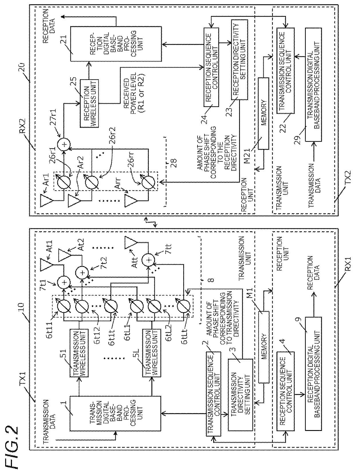
A wireless receiver measures a reception parameter while scanning multiple pieces of reception directivity for an interval during which a signal is not transmitted from a wireless transmitter. The wireless transmitter transmits a signal while scanning multiple pieces of transmission directivity, and the wireless receives measures a reception parameter relating to reception of the signal and determines k pieces of transmission directivity that correspond to high-ranking k results, respectively, of the measurement that have a great reception parameter. The wireless transmitter forms any transmission directivity and transmits a signal, and the wireless receives measures a reception parameter while scanning M pieces of reception directivity and determines reception directivity that is to be used for data communication.

Description

BACKGROUND OF INVENTION1. Field of the Invention[0001]The present disclosure relates to a wireless communication system, a wireless communication apparatus and a directivity determination method that determine directivity relating to transmission and reception by wireless communication apparatuses that use a high frequency.2. Description of the Related Art[0002]In a high frequency band (for example, a Super High Frequency (SHF) band of 6 to 30 GHz or an Extremely High Frequency (EHF) band of 30 to 300 GHz) (the same is hereinafter true), which is considered as being allocated to the 5-th generation mobile communication system (5G), because a radio wave propagation loss is great, distances of propagation by wireless communication apparatus are limited to being short. The usual practice for alleviating this restraint is to apply a beamforming technology in which directivity of a radio wave is involved in transmission, reception, or transmission and reception (namely, a technology of f...

Claims


Application Information

Patent Timeline
Patent Type & Authority Patents(United States)
IPC IPC(8): H04B17/14H04B17/318H04B17/10
CPCH04B17/14H04B17/104H04B17/318H04B7/0695
Inventor KATO, OSAMUASANO, HIROAKIKANEMOTO, HIDEKI
Owner PANASONIC INTELLECTUAL PROPERTY MANAGEMENT CO LTD
Learn More