Transmission apparatus and transmission method

a transmission apparatus and transmission method technology, applied in the field of wireless communication, can solve the problems of achieve the effects of suppressing an increase in the overhead for reporting, flexible frequency scheduling, and increasing the overhead for reporting control signaling

Active Publication Date: 2021-07-06
PANASONIC INTELLECTUAL PROPERTY CORP OF AMERICA
View PDF6 Cites 0 Cited by
  • Summary
  • Abstract
  • Description
  • Claims
  • Application Information

AI Technical Summary

Benefits of technology

[0014]As flexibility in frequency scheduling increases, more signaling bits are needed to report control signaling (i.e., common control information, resource assignment information and per-user allocation information) to STAs. This results in an increase of the overhead for reporting control signaling. So there is a relationship of trade-off between flexibility in frequency scheduling and overhead for reporting control signaling. A challenge is how to achieve flexible frequency scheduling while suppressing an increase of the overhead for reporting the control signaling.
[0017]With the transmission apparatus and transmission method of the present disclosure, it is possible to achieve flexible frequency scheduling while suppressing an increase of the overhead for reporting the control signaling.

Problems solved by technology

This results in an increase of the overhead for reporting control signaling.
A challenge is how to achieve flexible frequency scheduling while suppressing an increase of the overhead for reporting the control signaling.

Method used


Image

  • Transmission apparatus and transmission method
  • Transmission apparatus and transmission method
  • Transmission apparatus and transmission method

Examples


first embodiment

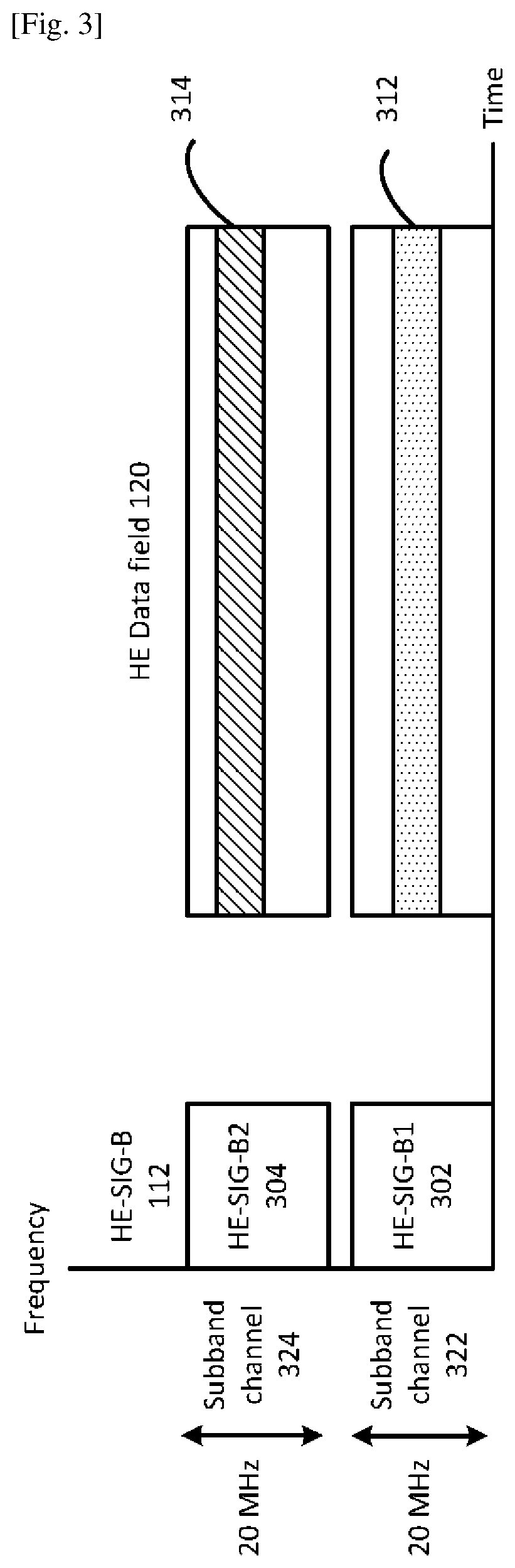
[0064]According to a first embodiment of the present disclosure, one or more last BCC blocks of the user-specific field of one HE-SIG-B channel field which is longer than the other HE-SIG-B channel field in length before appending the padding bits are relocated to the other HE-SIG-B channel. By this relocation, the number of HE-SIG-B symbols is minimized. Thus, overhead for reporting control signaling is reduced and channel efficiency is improved.

[0065]If the other HE-SIG-B channel field has a poor channel quality due to interference, the STAs whose corresponding BCC blocks are relocated to the other HE-SIG-B channel may not be able to decode resource allocation signaling in the other HE-SIG-B channel field properly and thus they cannot determine the number of original BCC blocks in the other HE-SIG-B channel field. In this case, if the relocated BCC blocks are located immediately after the original BCC blocks in the other HE-SIG-B channel field, the STAs cannot determine the start ...

second embodiment

[0082]According to a second embodiment of the present disclosure, one or more last BCC blocks of the user-specific field of one HE-SIG-B channel field which is longer than the other HE-SIG-B channel field in length before appending the padding bits are relocated to the other HE-SIG-B channel field so that the number of HE-SIG-B symbols is minimized. Thus overhead for reporting control signaling is reduced and channel efficiency is improved.

[0083]According to the second embodiment of the present disclosure, the relocated BCC blocks are located at a predetermined position of the other HE-SIG-B channel field (e.g., at the end of the other HE-SIG-B channel field). The relocated BCC blocks may be transmitted with a more robust MCS than the MCS used for other BCC blocks. As a result, even if the other HE-SIG-B channel field has a poor channel quality due to interference, the STAs may still be able to decode the relocated BCC blocks properly.

[0084]According to the second embodiment of the ...

third embodiment

[0097]According to a third embodiment of the present disclosure, one or more last BCC blocks of the user-specific field of one HE-SIG-B channel field which is longer than the other HE-SIG-B channel field in length before appending the padding bits are relocated to the other HE-SIG-B channel field so that the number of HE-SIG-B symbols is minimized. Thus, overhead for reporting control signaling is reduced and channel efficiency is improved.

[0098]According to the third embodiment of the present disclosure, the relocated BCC blocks are located at a predetermined position of the other HE-SIG-B channel field (e.g., at the end of the other HE-SIG-B channel field). The relocated BCC blocks may be transmitted with higher power than the other BCC blocks. As a result, even if the other HE-SIG-B channel field has a poor channel quality due to interference, the STAs may still be able to decode the relocated BCC blocks properly. However, power boosting of the relocated BCC blocks may result in ...


PUM


Abstract

An transmission apparatus of the present disclosure comprises a transmission signal generator that generates a transmission signal including a legacy preamble, a non-legacy preamble and a data field and a transmitter that transmits the transmission signal. The non-legacy preamble comprises a first and a second signal fields, the second signal field comprising a first channel field and, when the transmission signal occupies more than one subband channel, the second signal field further comprising a second channel field. Each of the first and the second channel fields comprises a user-specific field that includes a plurality of user fields, each carrying per-user allocation information for a terminal station. The plurality of user fields are split equitably between the first and the second channel fields when a full bandwidth that covers a first and a second subband channels is allocated for multi-user MIMO transmission.

Description

TECHNICAL FIELD[0001]The present disclosure generally pertains to wireless communications and, more particularly, to a transmission apparatus and a transmission method for transmitting control signaling in a wireless communications system.BACKGROUND ART[0002]The IEEE (Institute of Electrical and Electronics Engineers) 802.11 Working Group is developing 802.11ax HE (High Efficiency) WLAN (Wireless Local Area Network) air interface in order to achieve a very substantial increase in the real-world throughput achieved by users in high density scenarios. OFDMA (Orthogonal Frequency Division Multiple Access) multiuser transmission has been envisioned as one of the most important features in 802.11ax. OFDMA is a multiple access scheme that performs multiple operations of data streams to and from the plurality of users over the time and frequency resources of the OFDM system.[0003]Studies are underway to perform frequency scheduling for OFDMA multiuser transmission in 802.11ax. According to...

Claims


Application Information

Patent Timeline
Patent Type & Authority Patents(United States)
IPC IPC(8): H04L5/00H04W28/06H04B7/0452
CPCH04L5/0037H04L5/0023H04L5/0094H04W28/06H04B7/0452H04W84/12H04L5/001H04L5/0053H04W72/23
Inventor HUANG, LEICHITRAKAR, ROJANURABE, YOSHIO
Owner PANASONIC INTELLECTUAL PROPERTY CORP OF AMERICA
Why Eureka
Try Eureka