Anatomy adapted acquisition with fixed multi-source x-ray system

a multi-source x-ray and acquisition system technology, applied in the field of multi-source x-ray imager control system, can solve the problems of limited detector frame speed, limitations, and many problems with multi-source x-ray imagers

Active Publication Date: 2021-07-27
KONINKLJIJKE PHILIPS NV
View PDF13 Cites 1 Cited by
  • Summary
  • Abstract
  • Description
  • Claims
  • Application Information

AI Technical Summary

Benefits of technology

[0009]According to one embodiment, the system comprises an instruction module configured to instruct the imager to acquire an image of the object along the optical axis of the target pair. The proposed system is particularly beneficial where a sequence of frames is to be acquired at different instants such as during a fluoroscopic or angiographic intervention or other. In particular, a frame for a given imaging instant is only acquired along optical axis or axes of the selected target imaging pair(s). The selection may be dynamically adapted during acquisition of the sequence. Only a true subset of all available imaging pairs is selected at any given imaging instant. This allows reducing the number of projections as only a (true) sub-set of imaging pair is selected from all possible imaging pairs. In on embodiment, as an extreme case, only a single imaging pair is selected at some or all imaging instants. Image quality and relevance is maintained however as the selection is based on the geometric structure of the object of interest. Frame rate can be increased in particular in imagers where a single detector is used In particular the frame rate for the currently selected viewing direction can be increased because interleaved acquisitions along (other) imaging directions are avoided. Cross-scatter can also be increased as fewer X-ray beams are crossing each other at any given imaging instant.

Problems solved by technology

Several issues have however been reported with these types of multi-source x-ray imagers.
Some limitations arise due to limited detector frame speed in the case where a single detector is used for instance.
Other issues include x-ray dose or cross scatter when using such multi-source x-ray imagers.

Method used


Image

  • Anatomy adapted acquisition with fixed multi-source x-ray system
  • Anatomy adapted acquisition with fixed multi-source x-ray system
  • Anatomy adapted acquisition with fixed multi-source x-ray system

Examples


Embodiment Construction

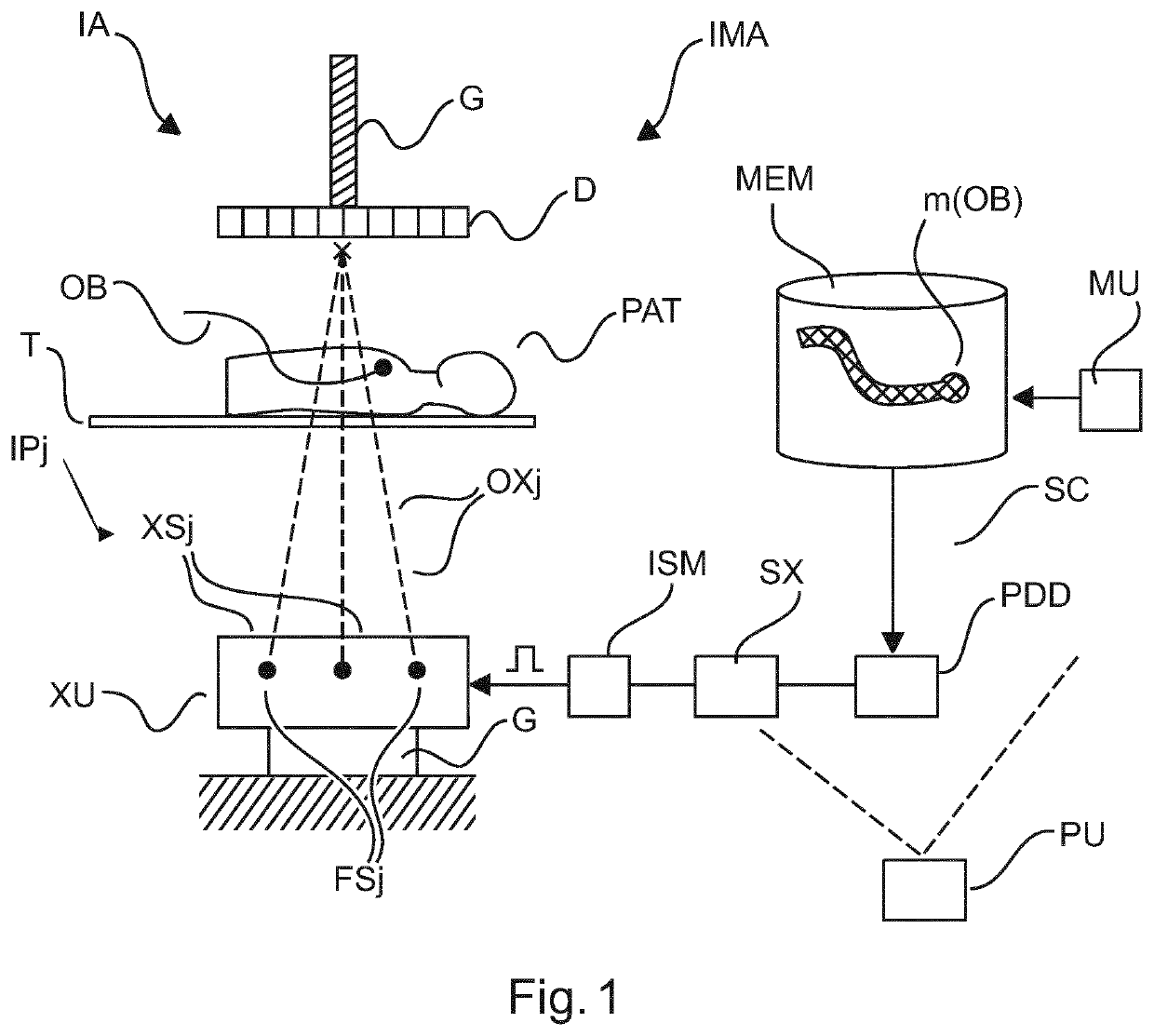
[0032]With reference to FIG. 1, there is shown a schematic block diagram of an imaging arrangement IMA comprising an X-ray imaging apparatus IA and a system SC for controlling operation of the imaging apparatus IA (referred to herein as the “imager”).

[0033]Applications of the imaging arrangement IMA envisaged herein include medical interventions where one or more objects OB such as a medical tool (catheters, guide wires, etc.) is / are introduced into a subject PAT, such as a human or animal patient.

[0034]The imager IA allows acquiring images of the inside of the patient PAT to verify position or orientation, etc., of the introduced object OB. For example's sake, the object may be a guide wire for use in cardiac intervention. The guide wire OB is introduced into the patient at a suitable entry point and is then forwarded to a target site such as valve of the heart. The guide wire is flexible and its flexure in particular the bending of its tip portion can be controlled from the outsid...


PUM


Abstract

A system (SC) for controlling operation of a multi-focal-spot X-ray imager (IA). The system comprises a projection direction determiner (PDD) configured to determine a projection direction for an object (OB) to be imaged, based on a geometric structure of a model m(OB) for the object (OB). A selector (SX) of the system is configured to select, from the imager (IA)'s plurality of focal-spot-detector pairs (IPj) with different optical axes (OXj), at least one target pair whose optical axis corresponds to the determined projection direction.

Description

CROSS-REFERENCE TO PRIOR APPLICATIONS[0001]This application is the U.S. National Phase application under 35 U.S.C. § 371 of International Application No. PCT / EP2017 / 060857, filed on May 8, 2017, which claims the benefit of European Patent Application No. 16169084.7, filed on May 11, 2016. These applications are hereby incorporated by reference herein.FIELD OF THE INVENTION[0002]The invention relates to a system for controlling operation of a multi-focal-spot X-ray imager, to a method of controlling operation of a multi-focal-spot X-ray imager, to an imaging arrangement, to a computer program element and to a computer readable medium.BACKGROUND OF THE INVENTION[0003]Multi-source x-ray imaging with a single embodiment detectors have been considered for interventional use. One such multi-source imaging system is disclosed in WO 2015 / 063191. Several issues have however been reported with these types of multi-source x-ray imagers. Some limitations arise due to limited detector frame spee...

Claims


Application Information

Patent Timeline
Patent Type & Authority Patents(United States)
IPC IPC(8): A61B6/00A61B6/12
CPCA61B6/4014A61B6/12A61B6/4028A61B6/4266A61B6/4464A61B6/487A61B6/545A61B6/4007A61B6/486A61B6/504A61B6/5264A61B6/547A61B6/587
Inventor SCHAEFER, DIRKGRASS, MICHAEL
Owner KONINKLJIJKE PHILIPS NV
Why Eureka
Try Eureka