Power generation system of a multi-converter wind turbine and control method thereof

a power generation system and multi-converter technology, applied in power conversion systems, reactive power adjustment/elimination/compensation, circuit arrangements, etc., can solve the problems of affecting both the normal operation of the wind turbine and the voltage transient, conflicting with the standard dynamic switching operation, and unable to meet the reactive power requirements. to achieve the effect of avoiding power glitches

Active Publication Date: 2021-08-03
GAMESA INNOVATION & TECH SA
View PDF15 Cites 0 Cited by
  • Summary
  • Abstract
  • Description
  • Claims
  • Application Information

AI Technical Summary

Benefits of technology

[0026]Notice that any preferred option and particular embodiment of the system and wind turbine of the invention can be applied to the method and computer program of the invention. Likewise, any preferred option and particular embodiment of the method and computer program of the invention can be applied to the system and wind turbine of the invention.
[0027]With the power generation system, wind turbine, control method and computer program of the invention, electric grid requirements in terms of reactive power quantity and response time are fulfilled, while optimizing the AEP advantages of dynamic switching. Furthermore, power glitches are minimized through dynamic management of each converter reactive power reference by control means. These and other advantages will be apparent at the light of the detailed description of the invention.

Problems solved by technology

However, current grid connection requirements demand power generation systems of wind turbines to deliver reactive power with strict requisites in terms of quantity and time response.
These requisites are often incompatible with dynamic switching strategies, as when some converters are disconnected due to low wind speed conditions, reactive power requirements cannot be fulfilled.
These issues affect both normal operation of the wind turbine and voltage transients.
These requirements create a conflict with the standard dynamic switching operation of the turbine, as the number of active converters vary depending on wind conditions.
Subsequently, conventional solutions force all converters to be connected at all times, losing the AEP advantages of dynamic switching.
In multi-converter topologies with dynamic switching, this issue is a problem because of some converters in low wind speeds are disconnected, so when a voltage dip is produced, the wind turbine are not be able to fulfill the required reactive current injection level.

Method used


Image

  • Power generation system of a multi-converter wind turbine and control method thereof
  • Power generation system of a multi-converter wind turbine and control method thereof
  • Power generation system of a multi-converter wind turbine and control method thereof

Examples


Embodiment Construction

[0034]The matters defined in this detailed description are provided to assist in a comprehensive understanding of the invention. Accordingly, those of ordinary skill in the art will recognize that variation changes and modifications of the embodiments described herein can be made without departing from the scope and spirit of the invention. Also, description of well-known functions and elements are omitted for clarity and conciseness.

[0035]Note that in this text, the term “comprises” and its derivations (such as “comprising”, etc.) should not be understood in an excluding sense, that is, these terms should not be interpreted as excluding the possibility that what is described and defined may include further elements, steps, etc.

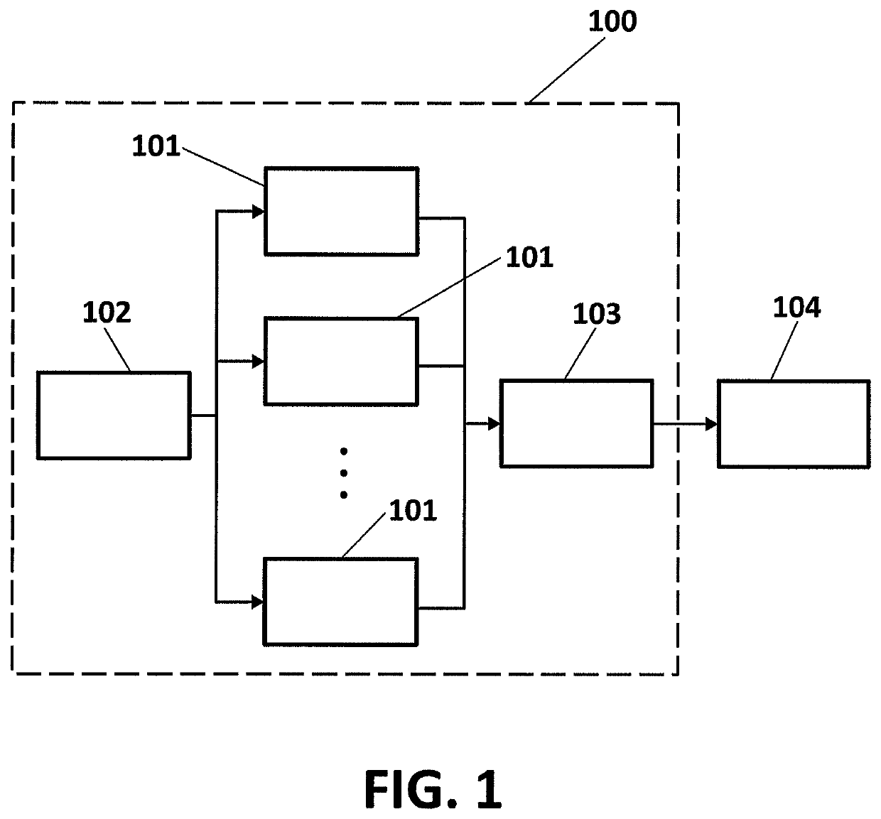
[0036]FIG. 1 shows a preferred embodiment of a multi-converter wind turbine (100), which comprises a preferred embodiment of the power generation system of the invention, and which implements a preferred embodiment of the method of the invention. In particula...


PUM


Abstract

Wind turbine comprising a plurality of converters, which are dynamically switched between at least a first standby state, a second running state, and a third state with an active direct current link. Converters are switched from the first standby state to the third state when a required reactive power is higher than a reactive power capability of converters on the second running state and when a voltage transient occurs.

Description

BACKGROUND OF THE INVENTIONField of the Invention[0001]The present invention has its application within the renewable energy sector and, especially, in the industrial area engaged in providing multi-converter wind turbines.Related Art[0002]Multi-converter wind turbine topologies enable to dynamically switch a plurality of independent converters between on an off states depending on wind conditions and target reactive power. For example, U.S. Pat. No. 7,928,592 B2 presents a multi-converter topology with isolated outputs of parallel converter threads through isolated power windings at the turbine generator, removing the circulating common mode current between converters and circumventing the need of a common mode inductor. In yet another example, U.S. Pat. No. 8,138,620 B2 presents an alternative multi-converter topology connected to an alternating current (AC) generator which monitors characteristics of the AC generator and applies several switching patterns to the converters accord...

Claims


Application Information

Patent Timeline
Patent Type & Authority Patents(United States)
IPC IPC(8): H02J3/38H02M5/458H02J3/18
CPCH02J3/386H02J3/1814H02M5/458Y02E10/76Y02E40/10H02J3/50H02J3/38
Inventor VALDERREY SANCHEZ, FERNANDOJIMENEZ BUENDIA, FRANCISCOALLEN MIGUEL, JOSE ANGEL
Owner GAMESA INNOVATION & TECH SA
Why Eureka
Try Eureka