Gas phase sample preparation for cryo-electron microscopy

a cryo-electron microscopy and gas phase technology, applied in the field of cryo-electron microscopy gas phase sample preparation, can solve the problems of large amount of sample required for x-ray crystallography, large amount of target molecules, and impracticality of x-ray crystallography, so as to reduce image acquisition time, increase sensitivity, and improve image resolution

Active Publication Date: 2021-08-17
WISCONSIN ALUMNI RES FOUND
View PDF8 Cites 3 Cited by
  • Summary
  • Abstract
  • Description
  • Claims
  • Application Information

AI Technical Summary

Benefits of technology

[0008]The present invention provides new methods for controllably forming a layer of amorphous ice and other frozen amorphous solids on a substrate, and also provides cryo-EM sample preparation methods and systems that utilize in vacuo vitrification. In certain aspects of the invention, formation of an amorphous solid layer is independent of the deposition of a sample to be analyzed, thus allowing for the generation of uniformly thick layer. Furthermore, the formation of an amorphous solid layer may be monitored during formation and any imperfection in the solid layer may be corrected using ion milling or related techniques. In certain aspects, the present invention is also able to provide cryo-EM sample preparation resulting in increased image resolution, decreased image acquisition time, and increased sensitivity.

Problems solved by technology

One such limitation is that a large amount of sample is required for X-ray crystallography.
This makes X-ray crystallography impractical in cases where it is difficult to generate large, highly pure quantities of the target molecule.
This technology has driven considerable interest, but it still has a number of limitations, including resolution that is still a factor of four less than what is theoretically possible (Glaeser, R. M., Nature Methods, 2016, 13(1):28-32).
The majority of limitations are due to sample preparation, which typically requires purification and vitrification.
However, in practice, the process of sample vitrification is far from ideal.
Unfortunately, currently existing sample preparation techniques impart a preferred orientation of the particles (due largely to particle migration to the air / water interface), and the particles often become deformed / stretched at the air-water interface, thereby destroying the required structural heterogeneity.
This imposes a significant problem as conventional preparation techniques yield only a very few particles per grid hole.
First is that the majority of the sample gets removed during the blotting process.
Second, formation of ice in conventional methods causes the ice at the center of a hole in the grid to be thinner than the ice near the edges, forcing the particles to the outer edges.
Beyond limiting the scope and types of proteins that can be analyzed, conventional approaches puts a significant strain on the computational resources required to analyze the data Cheng et al., Cell, 2015, 161(3):438-449).

Method used


Image

  • Gas phase sample preparation for cryo-electron microscopy
  • Gas phase sample preparation for cryo-electron microscopy
  • Gas phase sample preparation for cryo-electron microscopy

Examples


example 1

ample Preparation Instruments

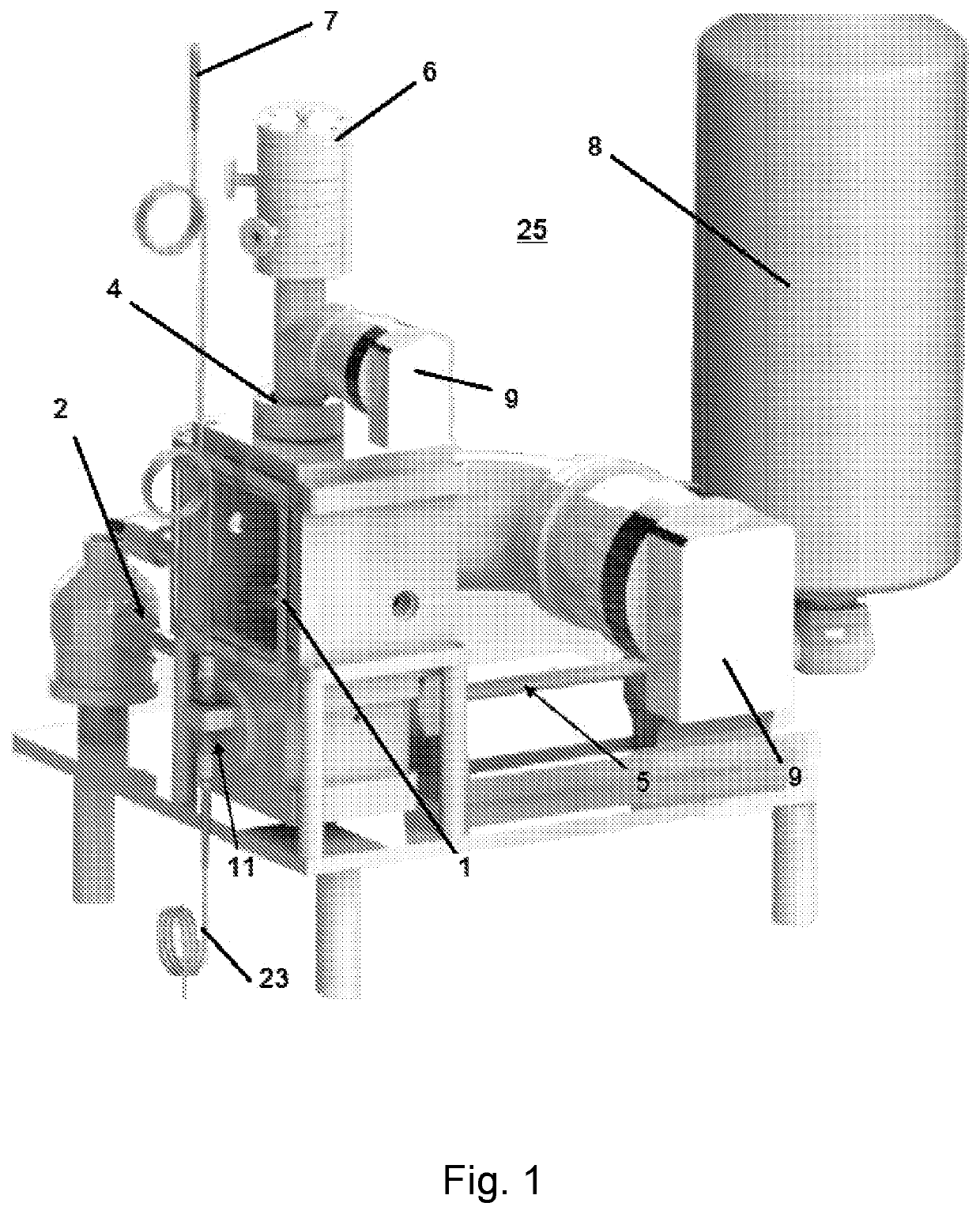
[0044]FIGS. 1-5 and 14-16 show exemplary cryo-electron microscopy (cryo-EM) sample preparation systems 25 according to certain embodiments of the present invention. A cryo-EM probe 2 able to hold or contain a sample is inserted into vacuum chamber 1. The temperature of the system is maintained using a coolant, such as liquid nitrogen, which is stored in tank 8 and transferred through cold finger 5, while one or more turbo pumps 9 are used to maintain the vacuum.

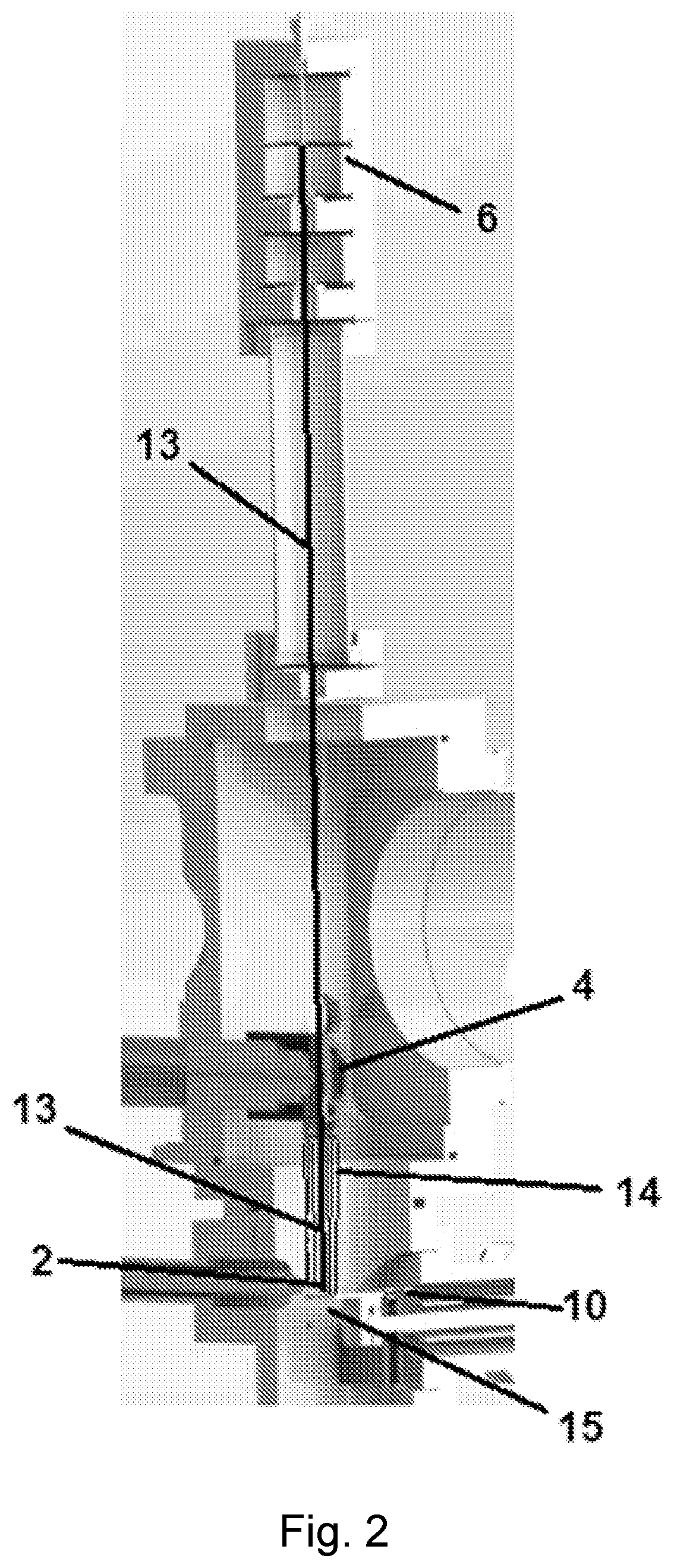
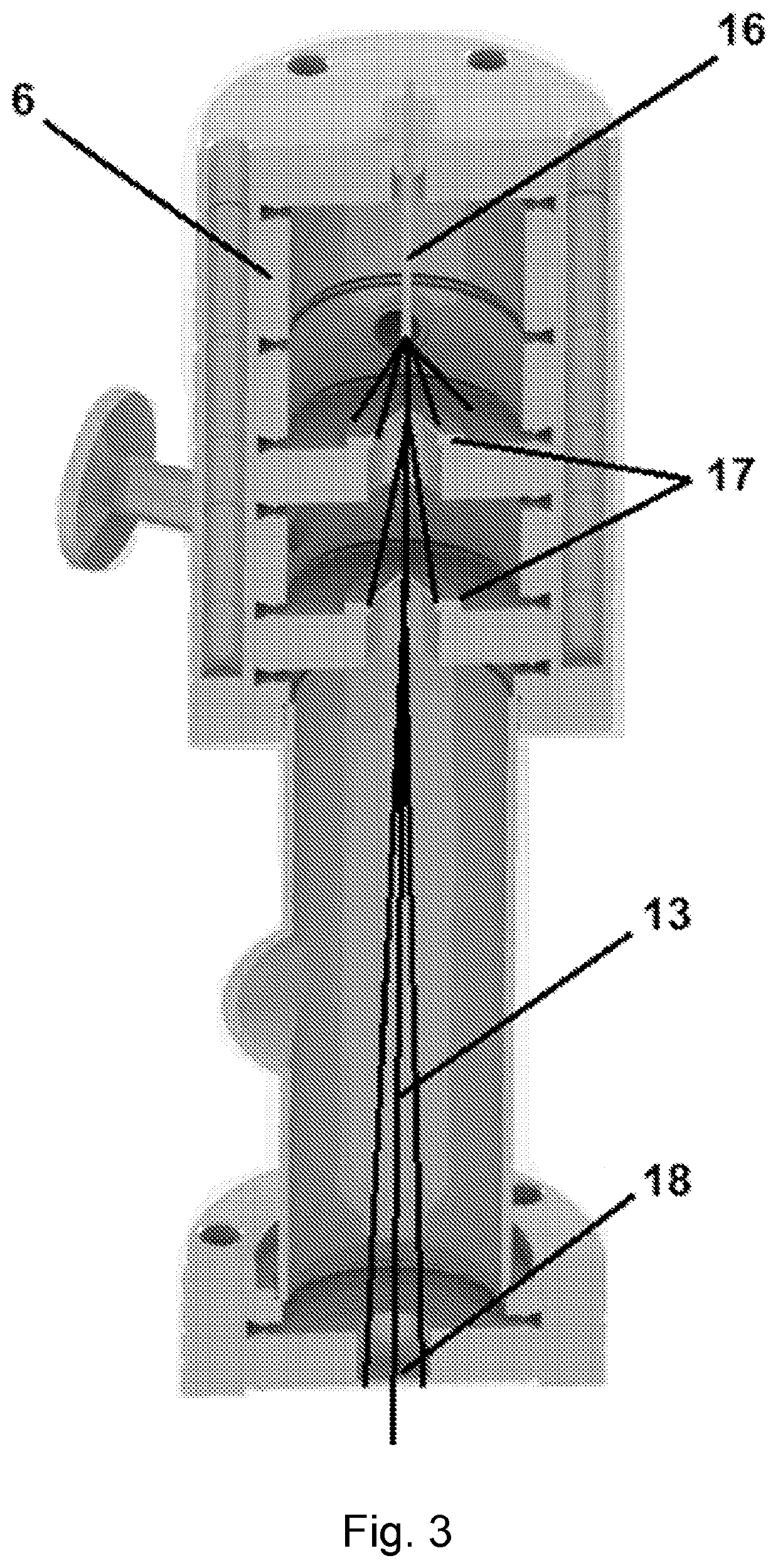
[0045]Analyte particles are collected in an analyte source 6 where they are focused into an analyte beam 13 (such as through electrospray ion deposition) and directed to contact the sample plate being held by cryo-EM probe 2 (see FIG. 2). FIG. 3 shows one type of an analyte source 6 where analyte ions or molecules are drawn into the analyte source 6 through capillary 16. One or more ion optic devices, such as skimmers 17, are used to focus the analyte ions into a beam 13 and to control the release...

example 2

Analyte Purification

[0049]Protein ions can be purified in the gas-phase, collected in vacuo, and, once removed from the vacuum, retain their enzymatic function (Blake et al., Analytical Chemistry, 2004, 76(21):6293-6305). Following these experiments, a mass spectrometer was modified so that analyte protein ions could be purified and deposited directly onto a sample probe. The probe surface originally comprised glycerol on stainless steel; however, with the requested cryo-transfer probe, the purified protein ions are deposited directly onto a cryogenic EM grid that has previously been covered in vitreous ice. Formation of the ice layer independent of the sample allows for the generation uniformly thick ice. Any imperfection in the ice may be corrected using ion milling or related techniques. Independently forming the ice also allows for appropriate quality control measures prior to committing the sample.

[0050]Vitreous ice undergoes a phase transition from high density amorphous (HDA)...

example 3

of Amorphous Ice

[0051]The present invention provides methods and instruments for preparing samples of an analyte with amorphous solids for use in cryo-electron microscopy (cryo-EM). The amorphous solids, which protect the analyte from radiation damage and dehydration during imaging, must remain transparent to the electron beam during EM. This requires the amorphous solid layer (e.g., the ice layer) be thin, on the order of the same thickness of the molecules to be analyzed, and the solid must be amorphous. If the amorphous solid becomes too thick, the electrons may be scattered causing defocusing and reduction in image contrast. If ordered crystals, such as crystalline ice, begin to form, the electrons will be diffracted and the resulting diffraction pattern will obscure the image (Cheng et al., Cell, 2015, 161(3): 438-449). The difficulties associated with forming vitrified sample as described above are well known in the art.

[0052]Probably less well known is the importance that vit...


PUM

PropertyMeasurementUnit
thicknessaaaaaaaaaa
temperatureaaaaaaaaaa
pressureaaaaaaaaaa

Abstract

The present invention provides methods for controllably forming a layer of amorphous ice and other amorphous solids on a substrate, and also provides cryoelectron microscopy (cryo-EM) sample preparation methods and systems that utilize in vacuo formation of amorphous ice and other solids. Formation of the amorphous solid layer can be independent of the deposition of sample molecules to be analyzed using electron microscopy, and allows for the generation of a uniformly thick layer. Optionally, mass spectrometry instruments are used to generate and purify molecules deposited on the generated amorphous solid layer. The techniques and systems described herein can deliver near ideal cryo-EM sample preparation to greatly increase resolution, sensitivity, scope, and throughput of cryo-EM protein imaging, and therefore greatly impact the field of structural biology.

Description

CROSS-REFERENCE TO RELATED APPLICATIONS[0001]This application is a U.S. National Stage Application filed under 35 U.S.C. § 371 of International Application No. PCT / US2018 / 041120, filed Jul. 6, 2018, which claims the benefit of U.S. Provisional Patent Application No. 62 / 529,778, filed Jul. 7, 2017. Both of these applications are hereby incorporated by reference in their entireties.STATEMENT REGARDING FEDERALLY SPONSORED RESEARCH OR DEVELOPMENT[0002]This invention was made with government support under GM118110 awarded by the National Institutes of Health. The government has certain rights in the invention.BACKGROUND OF THE INVENTION[0003]X-ray crystallography has traditionally been the standard for providing structural analysis for biological research, and while X-ray crystallography still provides high resolution structural information, this technique has several downsides. One such limitation is that a large amount of sample is required for X-ray crystallography. This makes X-ray c...

Claims


Application Information

Patent Timeline
Patent Type & Authority Patents(United States)
IPC IPC(8): G01N1/42G01N1/36H01J37/26H01J37/28G01N15/14H01J49/16
CPCG01N1/42G01N1/36G01N15/1468H01J37/26H01J37/28H01J49/164H01J49/165H01J2237/31745G01N2015/0038
Inventor COON, JOSHUAWESTPHALL, MICHAEL
Owner WISCONSIN ALUMNI RES FOUND
Why Eureka
Try Eureka