Tamping unit and method for tamping sleepers of a track

a track and sleeper technology, applied in the direction of track superstructure, roads, constructions, etc., can solve the problems of damage large force transmitted to the tamping tools, etc., and achieve the effect of increasing the efficiency of the tamping unit and preventing the damping effect of hydraulic lines

Active Publication Date: 2021-08-31
PLASSER & THEURER EXPORT VON BAHNBAUMASCHINEN GESELLSCHAFT MBH
View PDF21 Cites 2 Cited by
  • Summary
  • Abstract
  • Description
  • Claims
  • Application Information

AI Technical Summary

Benefits of technology

[0008]The invention provides that a vibration drive is associated with the drive for lowering the tool carrier, the vibration drive setting the tamping tools in a vibration which is effective vertically. An essential advantage here lies in the fact that an easier penetration of the tamping tools into the ballast takes place. As a result of the vertical vibration, the immersion impact is weaker. This causes less wear at the tamping tools, the service intervals become longer, and the strain at the bearings of the tamping unit is reduced. The optimal frequency of the vertical vibration is around 35 Hz.
[0010]In this, it is advantageous if a servo valve or proportional valve activated by means of a control is arranged at the hydraulic cylinder. Such valves are suitable for a pulsing control, wherein the mounting directly on the hydraulic cylinder precludes a damping effect of hydraulic lines.
[0011]It is also advantageous if the vertically effective vibration is switched on automatically during immersion and switched off automatically upon reaching a pre-set tamping depth or at the beginning of squeezing of the tamping tools. This results in an increase of efficiency of the tamping unit, wherein the squeezing motion of the tamping tools takes place in the proven manner.

Problems solved by technology

During this, great forces are transmitted to the tamping tools; in particular, when tamping a ballast bed which has not been renewed and is often totally encrusted, a high immersion resistance often has to be surmounted during penetration of the ballast bed, and occasionally damage to the tamping tools can occur.

Method used


Image

  • Tamping unit and method for tamping sleepers of a track

Examples


Embodiment Construction

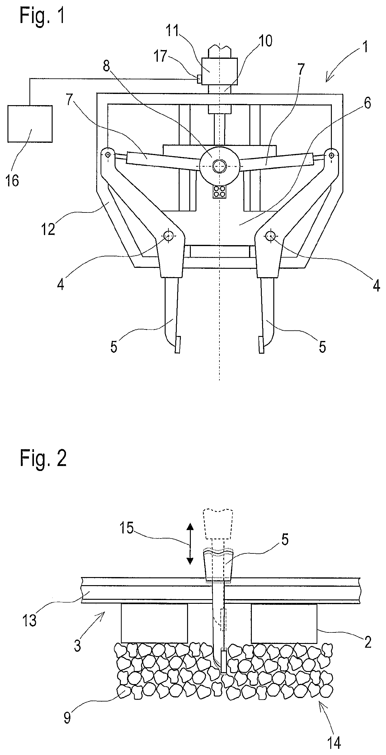
[0015]A tamping unit 1, shown in a simplified way in FIG. 1, for tamping sleepers 2 of a track 3 has pairs of two tamping tools 5 each, pivotable about a pivot axis 4, which are mounted on a tool carrier 6 and are each connected to a squeezing drive 7. Each squeezing drive 7 is connected to a vibration drive 8 designed as an eccentric. With this, horizontal vibration oscillations are produced which are transmitted via the squeezing drive 7 and the respective tamping tool 5 to the ballast 9 to be compacted. The tool carrier 6 is mounted on an assembly frame 12 for vertical adjustment by means of a drive 10 having an associated vibration drive 11. A servo valve 17 including a control 16 is associated with the drive 10.

[0016]Shown in FIG. 2 is a track 3 with a ballast bed 14, the track comprising rails 13 and sleepers 2. The tamping tool 5 designed to be set in a vertical vibration by the vibration drive 11 (arrow 15) is moved during the immersion procedure by means of the drive 10 fro...


PUM


Abstract

The invention relates to a tamping unit (1) for tamping sleepers (2) of a track (3), having a tool carrier (6) mounted on an assembly frame (12) for vertical adjustment by means of a drive (10), having pairs of two oppositely positioned tamping tools (5) which are squeezable towards one another about a respective pivot axis (4) as well as designed to be set in vibrations by a vibration drive (8). In this, it is provided that a vibration drive (11) is associated with the drive (10), the vibration drive setting the tamping tools in a vibration which is effective vertically.

Description

CROSS REFERENCE TO RELATED APPLICATIONS[0001]This application is the National Stage of PCT / EP2017 / 001056 filed on Sep. 7, 2017, which claims priority under 35 U.S.C. § 119 of Austrian Application No. A 457 / 2016 filed on Oct. 4, 2016, the disclosure of which is incorporated by reference. The international application under PCT article 21(2) was not published in English.FIELD OF TECHNOLOGY[0002]The invention relates to a tamping unit for tamping sleepers of a track, having a tool carrier mounted on an assembly frame for vertical adjustment by means of a drive, having pairs of two oppositely positioned tamping tools which are squeezable towards one another about a respective pivot axis as well as designed to be set in vibrations by a vibration drive. The invention additionally relates to a method for tamping sleepers of a track by means of the tamping unit.PRIOR ART[0003]Tamping units for tamping sleepers of a track are already well known, such as, for example from AT 500 972 B1 or AT ...

Claims


Application Information

Patent Timeline
Patent Type & Authority Patents(United States)
IPC IPC(8): E01B27/16
CPCE01B27/16E01B27/17E01B2203/12
Inventor SPRINGER, HEINZ
Owner PLASSER & THEURER EXPORT VON BAHNBAUMASCHINEN GESELLSCHAFT MBH
Why Eureka
Try Eureka