Mounting bracket for wall mounted items

a wall mounted and bracket technology, applied in the direction of display means, instruments, show hangers, etc., can solve the problems of easy removal of signs, damage to walls, and difficult removal of signs, so as to achieve no damage or residue on the wall, easy removal, and no damage to the effect of the wall

Active Publication Date: 2021-09-14
SCHWAAB
View PDF26 Cites 4 Cited by
  • Summary
  • Abstract
  • Description
  • Claims
  • Application Information

AI Technical Summary

Benefits of technology

[0005]Applicant's invention solves the problems stated above by utilizing a unique mounting bracket that can be used to mount signs, picture frames, hooks or other items on a wall, door or other substantially flat surface. Applicant's inventive mounting bracket allows the bracket and frame to be easily removed leaving no residue on the wall and no damage the wall.
[0006]Thus, it is an object of this invention to provide a bracket that can mount various objects such as a sign, picture frame, or hook to a wall, yet easily be removed leaving no damage to or residue on the wall.

Problems solved by technology

In order to remove the sign, the screws or nails must be removed from the wall making removal difficult.
Another problem with this method is that it damages the wall by leaving holes Where the screw or nail was inserted into the wall.
The problem with this method is that the sign can be easily removed by anyone, even by unauthorized persons.
This presents security issues due to the ease with which the sign can be removed, whereas Applicant's invention provides a more secure sign as compared to merely hanging a sign from a hook.
The same problems are encountered with mounting a picture frame as described above in mounting a sign.
Generally, the means to mount picture frames is to use hooks, nails or adhesives, none of which adequately solve the problems discussed above.
However, if a tensile force, perpendicular to the wall, is applied to the adhesive fastener, the adhesive fastener does not easily release until a great force is applied to the fastener sufficient to pull the fastener from the wall which generally means removing a portion of the wall surface along with the adhesive fastener.
There is an advantage and disadvantage to using these adhesive fasteners.
However, if the user does not properly apply a shear force to the fasteners to remove them from a wall, and instead apply a tensile force, damage to the wall surface certainly results.

Method used


Image

  • Mounting bracket for wall mounted items
  • Mounting bracket for wall mounted items
  • Mounting bracket for wall mounted items

Examples


Embodiment Construction

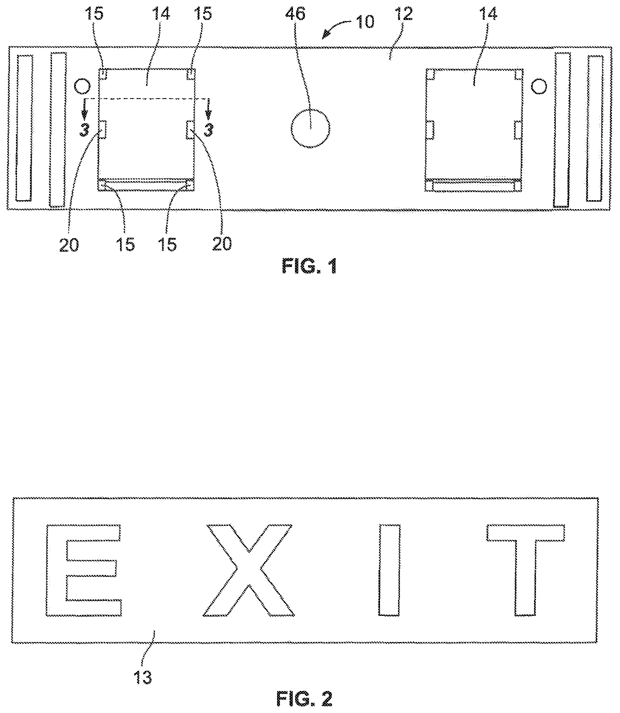
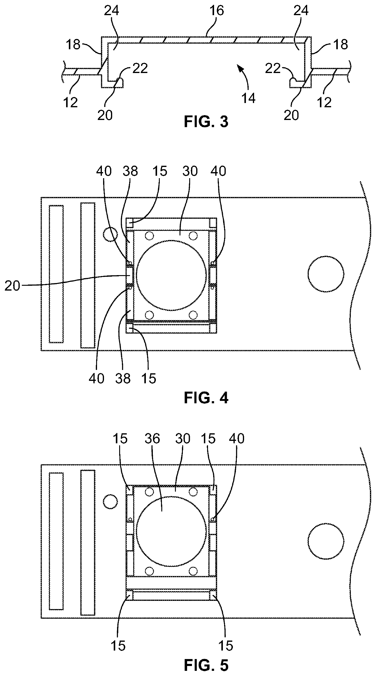
[0021]Turning first to FIG. 1, there is illustrated the rear view of a wall sign 10. Throughout this application, the reference to a “wall sign” is meant to include a wall sign, picture frame, wall mounted hook or fastener, or other similar objects that are intended to be releasably attached to a wall or similar substantially flat surface. There is a sign frame 12 having a pair of opposite recessed portions 14 on either end of the sign frame 12. There are tabs 15 in the corners of the recessed portion 14 the function of which will be described herein later. The sign frame receives a sign insert 13 (FIG. 2) containing the information to be conveyed to the observer. The sign insert 13 can be paper, cardboard, plastic or other material that serves the purpose for which it is intended such as providing information to the observer. As seen in FIG. 3, the recessed portion 14 has a back wall 16 and side walls 18. A pair of legs 20 at a free end of the side walls 18 extend inward from the s...


PUM


Abstract

A mounting bracket for releasably mounting an article such as a sign or picture frame to a substantially flat surface such as a wall. The bracket has an adhesive disc securely attached to one side of the bracket and the opposite side of the adhesive disc has a releasable adhesive face for attaching to the wall. A tool inserted into the mounting bracket applies a rotative force to the mounting bracket for applying a shear force to the releasable adhesive face which causes the adhesive face to release from the wall. The mounting bracket is releasably mounted to a sign, which allows easy installation and removal of the sign from the wall.

Description

CROSS-REFERENCE TO RELATED APPLICATIONS[0001]This application is based on and claims priority of provisional patent application 62 / 796,192 filed Jan. 24, 2019.BACKGROUND AND SUMMARY OF THE INVENTION[0002]This invention relates to a unique bracket and system for mounting wall signs, photographs, posters, and other items of the type that are often found in offices, retail establishments, commercial establishments, factories and homes.[0003]One embodiment of the present invention is designed for mounting wall signs. Wall signs are generally made to be permanently or semi-permanently affixed to a wall or door. Adhesives, nails, screws, hooks or other fasteners are commonly used. One method of mounting is to affix the sign to the wall by means of screws or nails that pass through the sign plate into the wall. In order to remove the sign, the screws or nails must be removed from the wall making removal difficult. Another problem with this method is that it damages the wall by leaving hole...

Claims


Application Information

Patent Timeline
Patent Type & Authority Patents(United States)
IPC IPC(8): A47F5/08F16M13/02F16M11/04
CPCA47F5/0846F16M13/02F16M11/04G09F2007/1847G09F7/20G09F7/18
Inventor PETERSEN, CRAIG
Owner SCHWAAB
Why Eureka
Try Eureka