
Motorized wheelchair chassis and motorized wheelchair comprising the same

a motorized wheelchair and chassis technology, applied in wheelchairs/patient conveyances, medical transportation, ambulance services, etc., can solve the problems of limited traction and driving comfort, relative pivoting movement of the frame element with respect to the battery support assembly only possible, etc., to improve serviceability, improve traction, and improve driving comfort

Active Publication Date: 2021-09-21
INVACARE INT GMBH
View PDF24 Cites 0 Cited by
  • Summary
  • Abstract
  • Description
  • Claims
  • Application Information

AI Technical Summary

Benefits of technology

[0006]More specifically, an aim of the present invention is to provide such a motorized wheelchair chassis that provides even better traction.
[0007]Yet another aim of the invention is to provide a motorized wheelchair chassis that provides improved driving comfort.
[0008]A further aim of the invention is to provide a motorized wheelchair chassis that can be made even more compact.
[0009]Still another aim of the invention is to provide a motorized wheelchair chassis that provides further improvements in terms of serviceability, e.g. facilitates access to the batteries.
[0020]By way of preference, the at least one battery is accessible from a rear end of the battery support assembly, which facilitates maintenance operations and improves serviceability.

Problems solved by technology

One limitation of the aforementioned dual-swing suspension in particular resides in the fact that relative pivoting movement of the frame element with respect to the battery support assembly is only possible about two orthogonal axes as explained above.
This inherently leads to certain limitations in terms of traction and driving comfort, which may still be improved.

Method used


Image

  • Motorized wheelchair chassis and motorized wheelchair comprising the same
  • Motorized wheelchair chassis and motorized wheelchair comprising the same
  • Motorized wheelchair chassis and motorized wheelchair comprising the same

Examples

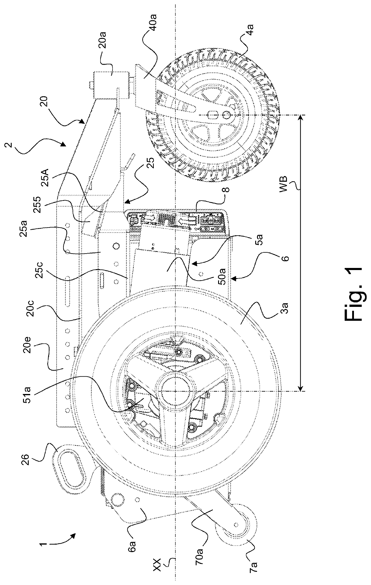
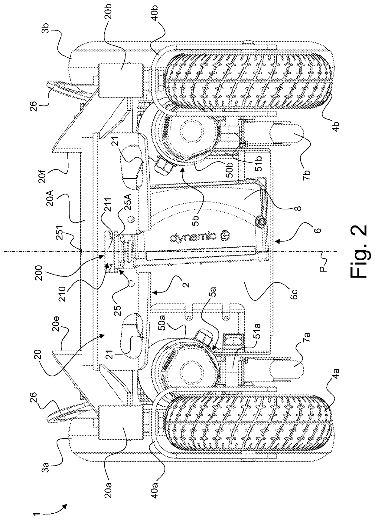
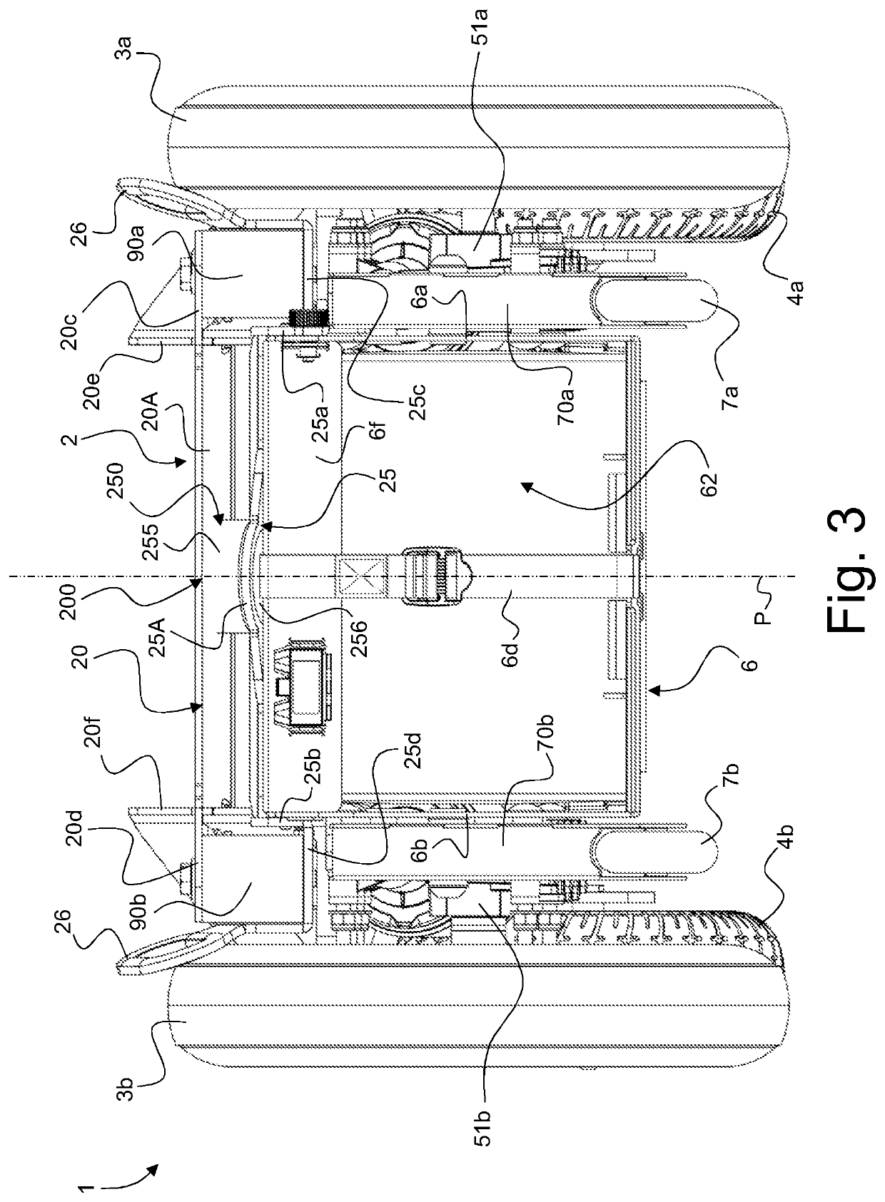

Embodiment Construction

[0031]The present invention will be described in relation to various illustrative embodiments. It shall be understood that the scope of the invention encompasses all combinations and sub-combinations of the features of the embodiments disclosed herein.

[0032]As described herein, when two or more parts or components are described as being connected, secured or coupled to one another, they can be so connected, secured or coupled directly to each other or through one or more intermediary parts.

[0033]The invention will be described in relation to various embodiments of a motorized wheelchair as depicted in FIGS. 1 to 7. FIGS. 1 to 7 actually show a motorized wheelchair chassis, designated globally by reference numeral 1, of the motorized wheelchair. It is to be understood that the motorized wheelchair chassis 1 would typically support a seat assembly, including a seat, and additional seat components such as armrests, legrest and / or footrests as well as further components, such as wheelch...


PUM


Abstract

A motorized wheelchair chassis includes a frame assembly having a first frame element that supports first and second caster wheels at an end of the first frame element. The first frame element is designed to support a seat assembly, a battery support assembly secured to an underside of the frame assembly, at least one battery, first and second power drive assemblies disposed on lateral sides of the battery support assembly, and first and second drive wheels driven by the first and second power drive assemblies, respectively. The frame assembly further comprises a second frame element that is secured to the battery support assembly. The first frame element is supported onto the second frame element via a coupling structure comprising a ball-joint bearing permitting relative movement of the first frame element with respect to the second frame element in more than two degrees of freedom within a limited range of movement.

Description

RELATED APPLICATIONS[0001]This application claims priority to European Patent Application No. 18207892.3, filed on Nov. 22, 2018, the entire disclosure of which is incorporated by reference in its entirety.TECHNICAL FIELD[0002]The present invention generally relates to a motorized wheelchair chassis and to a motorized wheelchair comprising the same.BACKGROUND OF THE INVENTION[0003]European Patent Publication No. EP 2 497 452 A1, which is incorporated herein by reference, discloses a motorized wheelchair chassis for a motorized wheelchair, which motorized wheelchair chassis comprises a frame assembly including a frame element that supports first and second caster wheels at a front end of the frame element, which frame element is designed to support a seat assembly. The motorized wheelchair chassis further comprises a battery support assembly secured to an underside of the frame assembly and supporting at least one battery, first and second power drive assemblies disposed on lateral s...

Claims


Application Information

Patent Timeline
Patent Type & Authority Patents(United States)
IPC IPC(8): A61G5/04A61G5/10
CPCA61G5/04A61G5/1078A61G5/06
Inventor PUSCHMANN, AXELJOST, PETERVERKAAIK, JULIAN KYLE
Owner INVACARE INT GMBH
Learn More