
Apparatus for omnidirectional locomotion

a technology of omnidirectional locomotion and apparatus, which is applied in the direction of mechanical pattern conversion, gymnastic exercise, instruments, etc., can solve the problems of high component cost, high mechanical failure risk, and high mechanical failure risk of omnidirectional treadmills, and achieves fast movement response, reduced apparatus weight, and reduced friction between sheet and frame

Active Publication Date: 2021-09-21
SONY MOBILE COMM INC
View PDF13 Cites 2 Cited by
  • Summary
  • Abstract
  • Description
  • Claims
  • Application Information

AI Technical Summary

Benefits of technology

[0007]Another objective is to provide an apparatus for omnidirectional locomotion of relatively simple and robust construction.
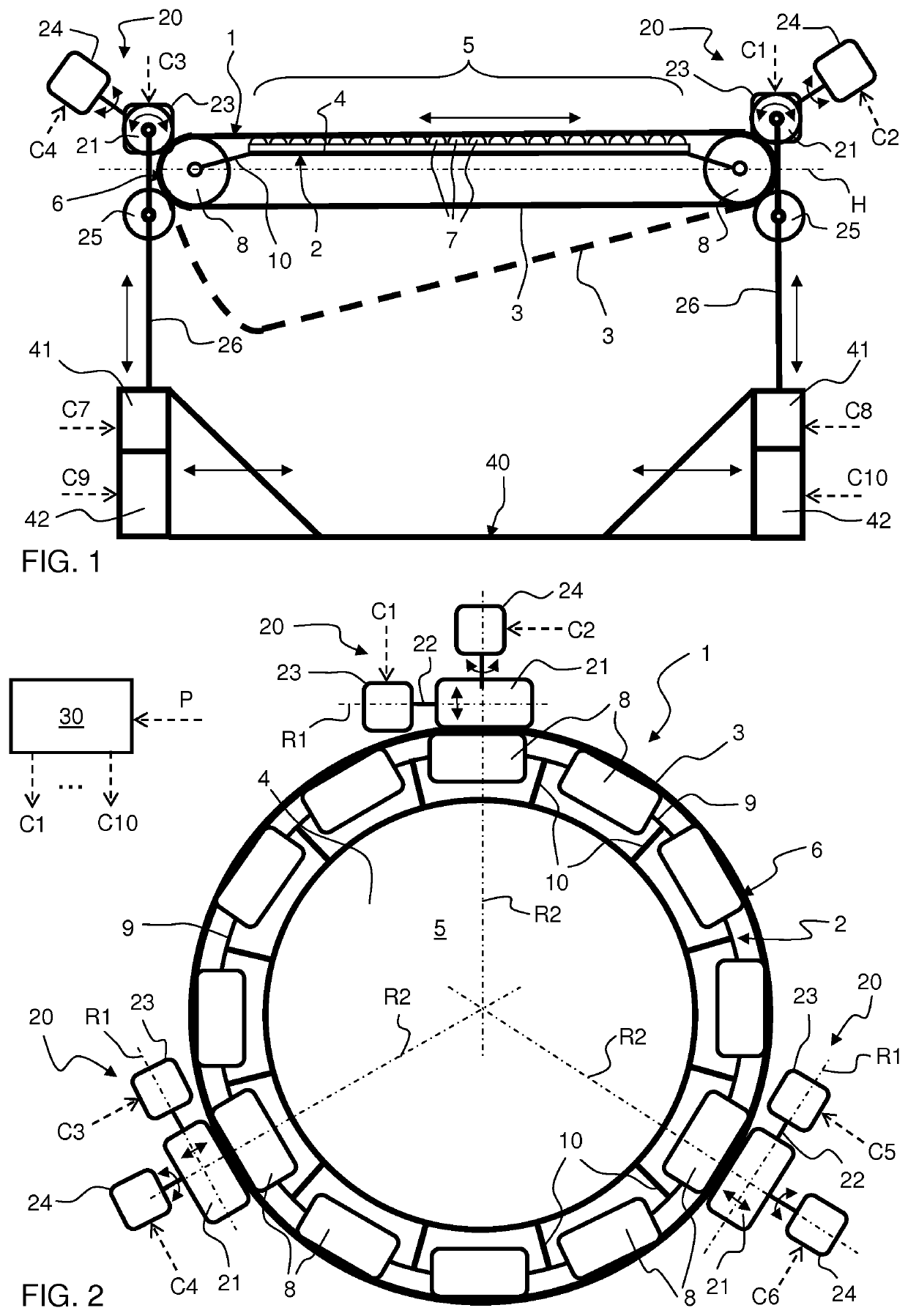
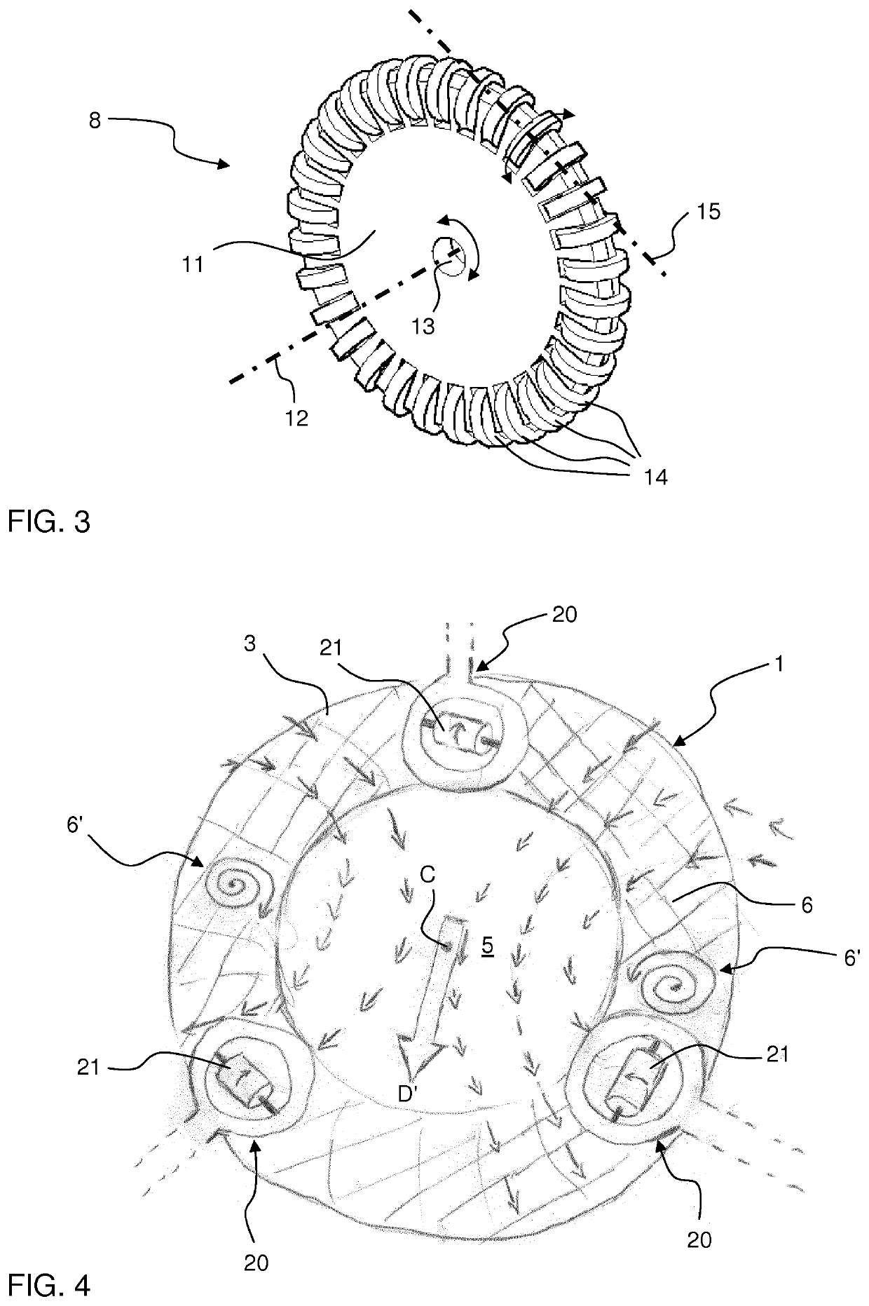
[0011]The apparatus employs a small number of actuated parts to provide the movable active surface. Basically, a continuous sheet is wrapped around the frame and driven to move around the frame by frictional contact at three or more spaced apart regions around the perimeter of the frame. With this basic design, the apparatus is simple and robust. By arranging the drive units to establish the frictional contact with the circumferential edge surface, i.e. in the vicinity of the active surface and in a region with relatively high tension in the continuous sheet, a fast movement response is achieved. In other words, the time period from a rotation of a drive roller to a movement of the active surface is small.
[0012]By driving the movement of the sheet by frictional contact at the edge surface, it is possible to employ a frame in the shape of a shell with an open bottom. This will reduce the weight of the apparatus, the friction between the sheet and the frame, and potentially facilitate handling and assembly.
[0013]The various embodiments described in the following provide additional technical effects and advantages, including providing simple and efficient movement control of the active surface, reducing friction between the sheet and the frame, improving the transfer of energy to the sheet by the frictional contact, providing firm support of the combination of sheet and frame, enabling inclination control of the active surface, facilitating assembly of the apparatus, and enhancing the experience of the user when moving on the active surface.
[0023]In one embodiment, at least one of the planar support surface and an inner surface of the continuous sheet facing the planar support surface is configured to reduce contact friction.

Problems solved by technology

The mechanical design of an omnidirectional treadmill is typically quite complex.
All of these constructions of the active surface involve a large number of actuated parts and therefore suffer from an elevated risk for mechanical failure and high component cost.
They are also likely to generate clatter and other disturbing noise during operation.
While this design proposal has the potential of overcoming the drawbacks listed above, it introduces a number of practical difficulties.
For example, it is a significant challenge to reduce friction between the sheet and the spheroid, especially since the weight of the user presses the sheet towards the flattened top surface of the spheroid and since the sheet needs to be stretched around the rounded edge surface of the spheroid.
Further, it is a challenge to establish sufficient frictional contact between the steerable roller and the sheet and to achieve a fast movement response of the active surface to the thrust vector generated by the steerable roller.
For example, if the steerable roller is pressed hard against the sheet to increase frictional contact, the sheet will simultaneously be pressed against the flat bottom surface, causing friction that restrains movement of the sheet around the spheroid.
Further, the design of the treadmill does not allow the active surface to be rotated, e.g. to untwine cables that are connected to the user or to user-worn equipment and that have become entangled by the user's movement on the active surface.

Method used


Image

  • Apparatus for omnidirectional locomotion
  • Apparatus for omnidirectional locomotion
  • Apparatus for omnidirectional locomotion

Examples


Embodiment Construction

[0046]Embodiments of the present invention will now be described more fully hereinafter with reference to the accompanying drawings, in which some, but not all, embodiments of the invention are shown. Indeed, the invention may be embodied in many different forms and should not be construed as limited to the embodiments set forth herein; rather, these embodiments are provided so that this disclosure may satisfy applicable legal requirements. Like numbers refer to like elements throughout.

[0047]Also, it will be understood that, where possible, any of the advantages, features, functions, devices, and / or operational aspects of any of the embodiments of the present invention described and / or contemplated herein may be included in any of the other embodiments of the present invention described and / or contemplated herein, and / or vice versa. In addition, where possible, any terms expressed in the singular form herein are meant to also include the plural form and / or vice versa, unless explic...


PUM


Abstract

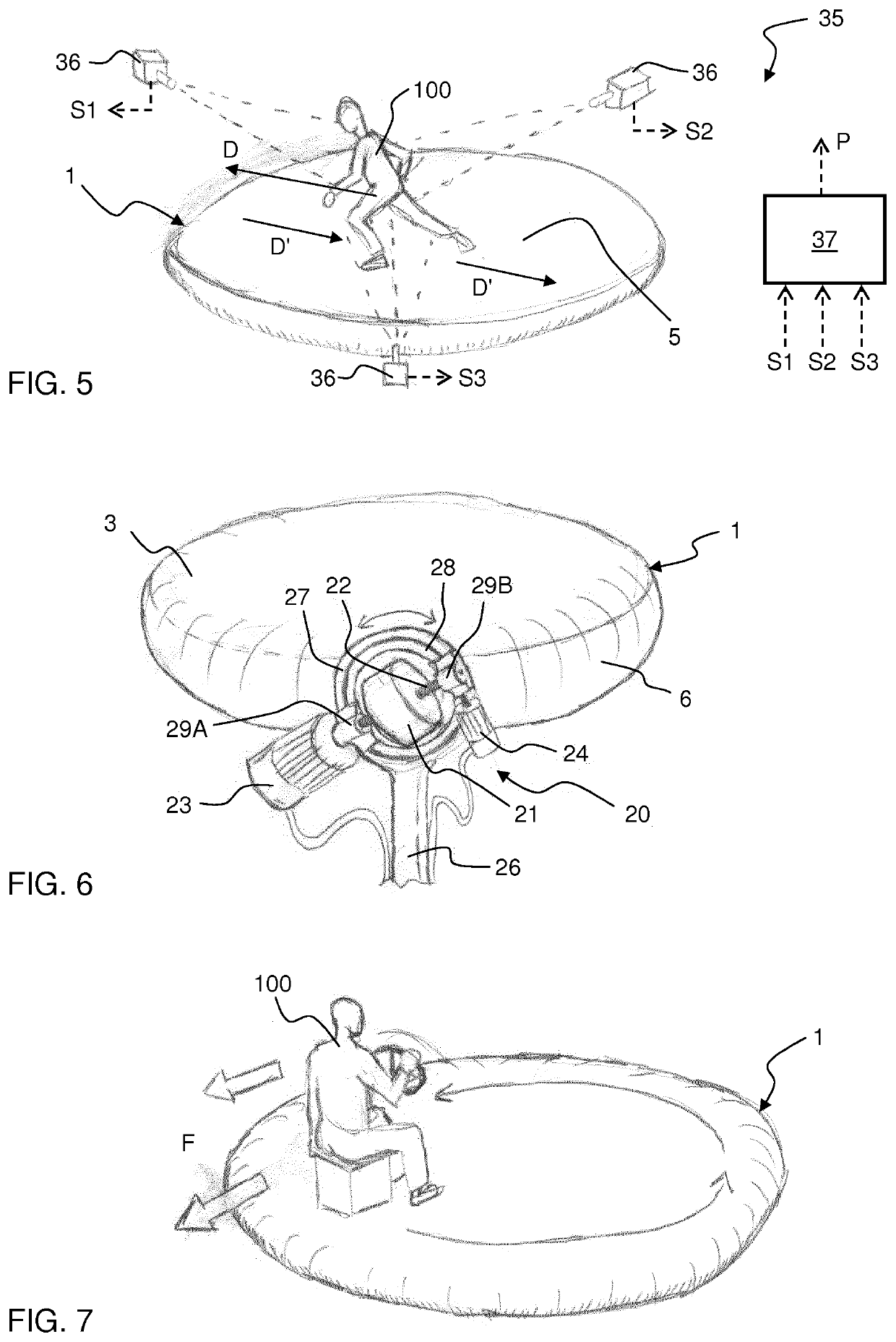
An apparatus, e.g. an omnidirectional treadmill, is configured to allow a user to move in an arbitrary direction. The apparatus comprises a platform (1) including a frame with a planar support surface for the user, and a continuous sheet (3) arranged to enclose the frame while extending along the planar support surface so as to define a moveable active surface (5). The apparatus further comprises a drive arrangement arranged in frictional contact with the sheet (3) to drive the sheet (3), and thus the active surface (5), in a given direction (D′) in relation to the planar support surface. The drive arrangement comprises at least three drive units (20) distributed around the frame, each drive unit (20) comprising a drive roller (21) arranged to rotatingly engage the sheet (3) in abutment to a circumferential edge surface (6) of the frame so as to establish the frictional contact with the sheet (3).

Description

TECHNICAL FIELD[0001]The present invention relates generally to devices that allow a user to perform locomotive motion in any direction, e.g. by walking, running, crawling or rolling. Such a device is commonly known in the art as an omnidirectional treadmill (ODT).BACKGROUND ART[0002]An omnidirectional treadmill is a mechanical device that allows for 360 degrees of locomotive movement by a user positioned on an active surface of the treadmill. Omnidirectional treadmills are typically motorized and operated by a control system so as to move the active surface under the user in synchronization with the locomotive movement of the user so as to maintain the user at a specific position on the treadmill. In other words, no matter which way the user moves, the active surface under the user will be controlled to move in the opposite direction. Thus, in contrast to traditional fitness-oriented treadmills that are designed to be linear (moving in one direction), omnidirectional treadmills nee...

Claims


Application Information

Patent Timeline
Patent Type & Authority Patents(United States)
IPC IPC(8): A63B22/02A63B22/00A63B24/00A63B71/06G06F3/01
CPCA63B22/025A63B22/0023A63B22/0285A63B24/0087G06F3/011A63B2022/0271A63B2024/0093A63B2071/0638A63B2210/10A63B2220/13A63B2220/72A63B2220/75A63B2220/76G06F2203/012
Inventor OLSSON, HENRIKDAHLROT, SVEN-ERIK
Owner SONY MOBILE COMM INC
Learn More