
Wind power generation device

a power generation device and wind power technology, applied in wind motors, renewable energy generation, greenhouse gas reduction, etc., can solve the problems of the vane below the rotating shaft not able to withstand wind, and achieve the effects of increasing pushing force, increasing rotation power, and generating more electrical power

Active Publication Date: 2021-10-12
NATIONAL TAIWAN NORMAL UNIVERSITY
View PDF4 Cites 0 Cited by
  • Summary
  • Abstract
  • Description
  • Claims
  • Application Information

AI Technical Summary

Benefits of technology

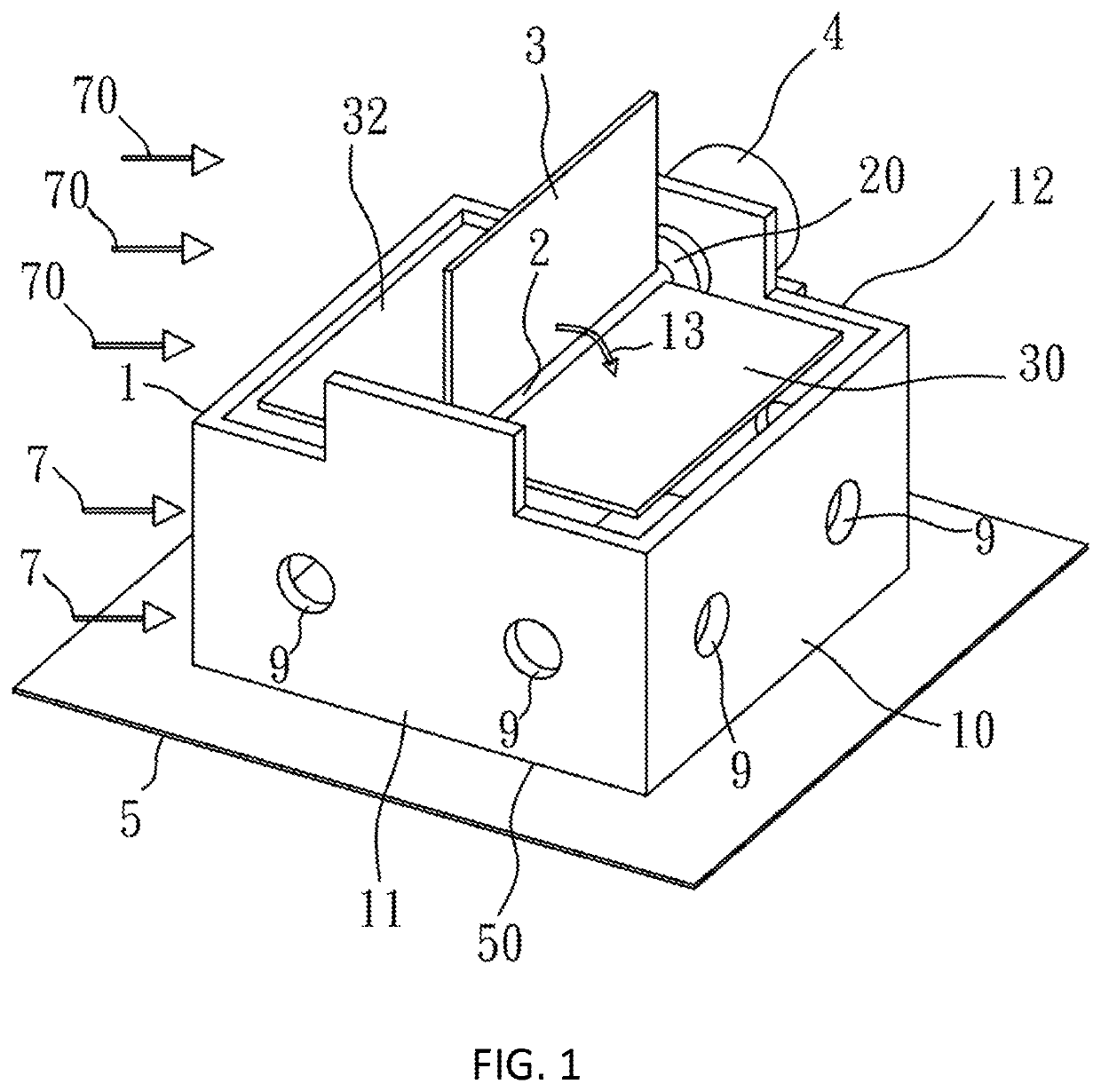
[0007]In order to solve the conventional problems, one of objectives of the present invention is to provide a wind power generation device which is able to control the rotating paddles in a horizontal paddle method to prevent from producing air resistance even in an upwind condition, so as to capture more wind power to generate more electrical power.
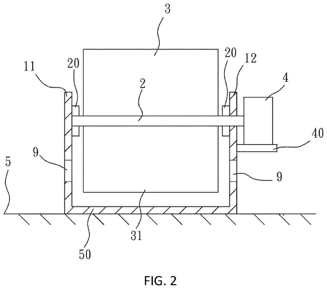
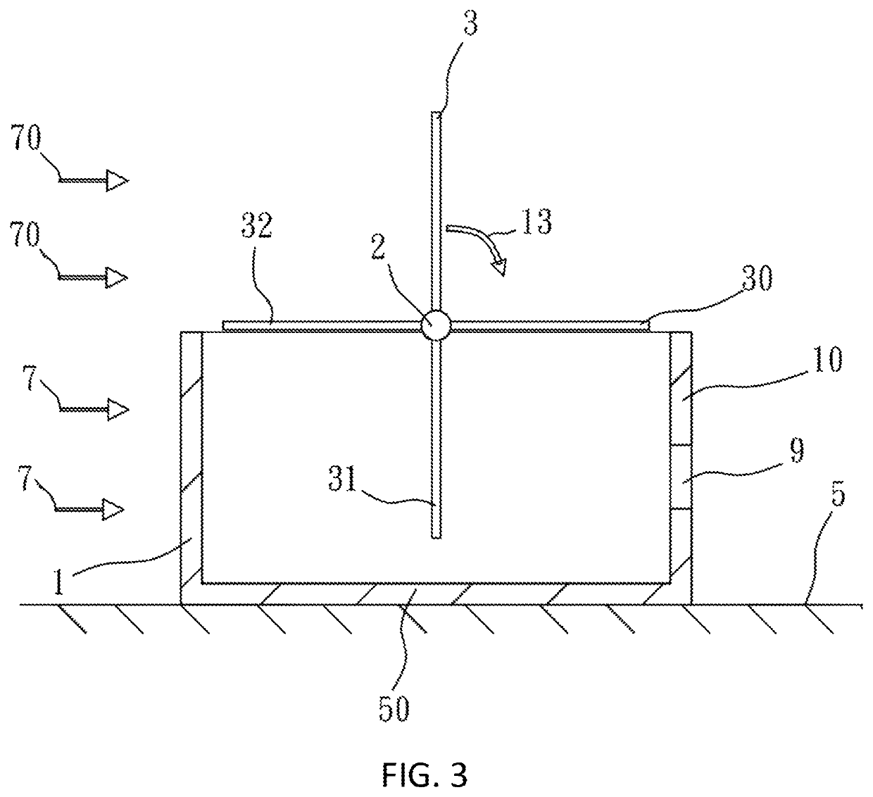
[0011]Furthermore, the rear plane, the left side plane, the right side plane of the wind blocking structure comprise a plurality of holes disposed thereon, so when the wind blows into the box-shaped structure to drive the vanes of the wind vane rotating body to rotate to below the rotating shaft, the air in the wind blocking structure is pressed, and the pushed and pressed air can flow out through the plurality of holes or gaps in the box-shaped structure, thereby reducing static air resistance.
[0013]Further, in order to further improve the power generation efficiency of the wind power generation device of the present invention, the wind power generation device of the present invention can include a structure for enlarging the area of the vane, thereby increasing the area of the vane of the wind vane rotating body in a downwind condition, and retracting the area of the vane to an original area in an upwind condition. Each of the two different sides of each of the plurality of vanes can be connected to an area enlarging structure, and a flexible cloth made of windproof material can be connected between the area enlarging structures on the two sides of the vane. According to an embodiment of the present invention, each of the plurality of area enlarging structures includes a hollow circular cylinder connected to the side of the vane, a circular rod retractable in the hollow circular cylinder, a connection plate connected to the flexible cloth and the circular rod, a link rod connected to the connection plate, and a pulley fixed with the link rod.
[0016]According to an embodiment of the present invention, the flexible cloth in the windward side can be extended in area to withstand pushing force of wind, and the circular rods connected to the remaining vanes, which are located below the rotating shaft, can be retracted into the hollow circular cylinders, and the flexible cloths connected thereto are not stretched and the remaining vanes are kept in the original areas thereof, so that the rotating shaft can have more rotation power because the enlarged area of the flexible cloth on the windward side, thereby increasing pushing force to drive the power generator to generate more electrical power.

Problems solved by technology

The front plate is in a flat plate shape and serves as a windward side of the box-shaped structure, and when wind appears in front of the wind blocking structure, the vane above the rotating shaft can withstand wind, and the other vanes below the rotating shaft do not withstand wind because the front plate of the wind blocking structure blocks the wind.

Method used


Image

  • Wind power generation device
  • Wind power generation device
  • Wind power generation device

Examples


Embodiment Construction

[0026]The following embodiments of the present invention are herein described in detail with reference to the accompanying drawings. These drawings show specific examples of the embodiments of the present invention. These embodiments are provided so that this disclosure will be thorough and complete, and will fully convey the scope of the invention to those skilled in the art. It is to be acknowledged that these embodiments are exemplary implementations and are not to be construed as limiting the scope of the present invention in any way. Further modifications to the disclosed embodiments, as well as other embodiments, are also included within the scope of the appended claims. These embodiments are provided so that this disclosure is thorough and complete, and fully conveys the inventive concept to those skilled in the art. Regarding the drawings, the relative proportions and ratios of elements in the drawings may be exaggerated or diminished in size for the sake of clarity and conv...


PUM


Abstract

A wind power generation device includes a wind blocking structure, which is in a box-shaped structure fixed on ground by a bottom plane thereof; a wind vane rotating body including a rotating shaft and vanes fixed on the rotating shaft and arranged at equal angle intervals, wherein the rotating shaft is mounted on two bearings of the wind blocking structure, and the vanes are rotatable inside the box-shaped structure; a power generator connected to the rotating shaft and fixed on the box-shaped structure by a linking plate. When wind blows to the wind blocking structure to rotate the wind vane rotating body, the power generator is driven by the rotating shaft to generate electrical power. The wind power generation device can include at least two wind vane rotating bodies, or area enlarging structures added on the vanes, to increase windward areas of the vanes.

Description

[0001]This application claims priority for Taiwan patent application no. 108128665 filed on Aug. 12, 2019, the content of which is incorporated by reference in its entirely.BACKGROUND OF THE INVENTION1. Field of the Invention[0002]The present invention relates to a wind power generation device, and particularly to a power generating device which utilizes vanes fixed on a rotating shaft of a wind vane rotating body to withstand wind, so that the rotating shaft can be rotated to drive a power generator to generate electrical power.2. Description of the Related Art[0003]The kinetic energy of air flow is called wind energy, which is a kind of reusable energy generated by air flow. In general, wind energy is a form of energy extracted from wind, for example, wind turbines can be used to generate electrical power, windmills can be used to generate mechanical power, wind pumps can be used to pump or drain water, or sails can be used to propel ships. In the Middle Ages and Ancient times, pe...

Claims


Application Information

Patent Timeline
Patent Type & Authority Patents(United States)
IPC IPC(8): F03D3/00F03D3/04F03D3/02F03D3/06
CPCF03D3/002F03D3/02F03D3/0454F03D3/0463F03D3/068F05B2240/14F05B2240/2212Y02E10/74
Inventor KUO, CHIN-GUOCHEN, JUNG-HSUANSHU, CHAO-FULIU, YA-CHIAO
Owner NATIONAL TAIWAN NORMAL UNIVERSITY
Learn More