
Aerodynamic feature for aft edge portions of thrust reverser lower bifurcation wall

a thrust reverser and aft edge technology, applied in the direction of jet propulsion plants, machines/engines, etc., can solve problems such as aerodynamic drag, and achieve the effect of preventing aerodynamic drag

Active Publication Date: 2017-11-21
ROHR INC
View PDF20 Cites 0 Cited by
  • Summary
  • Abstract
  • Description
  • Claims
  • Application Information

AI Technical Summary

Benefits of technology

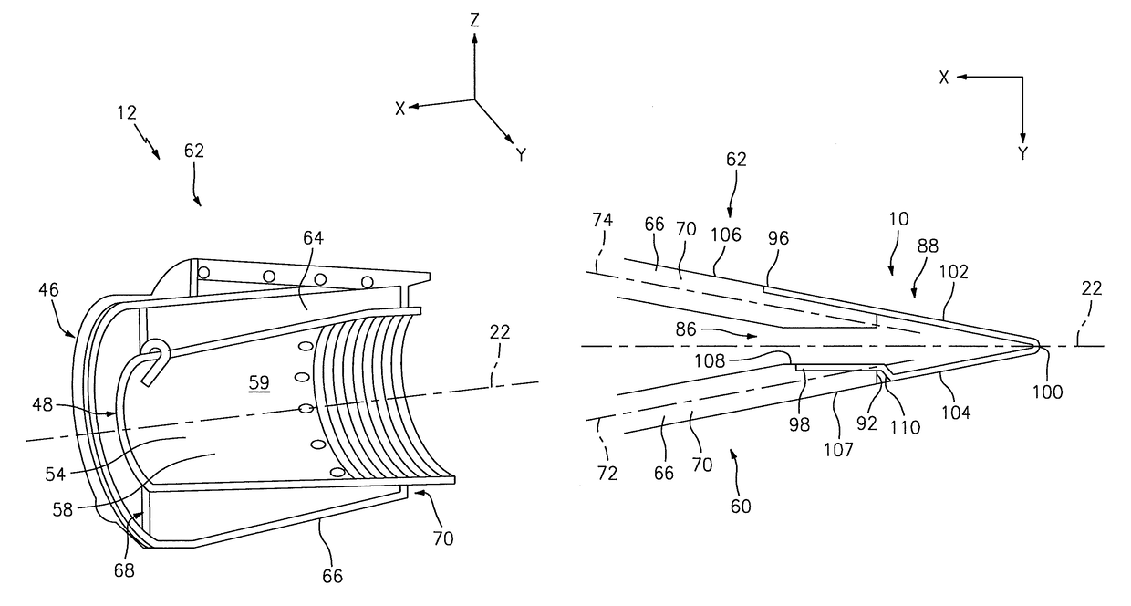
The present invention provides an improved thrust reverser for a propulsion system nacelle that includes a fixed structure and a translating structure. The fixed structure has an annular wall that partially defines an annular bypass airstream duct and is bifurcated into left and right side sections. The translating structure is moveable relative to the fixed structure and includes a ceramic flange disposed relative to an aft end portion of one of the lower bifurcation walls. The flange prevents aerodynamic drag and improves the efficiency of the thrust reverser.

Problems solved by technology

The respective aft edge portions of the lower bifurcation walls typically have a blunt, non-aerodynamic shape that can cause aerodynamic drag due to flow separation.

Method used


Image

  • Aerodynamic feature for aft edge portions of thrust reverser lower bifurcation wall
  • Aerodynamic feature for aft edge portions of thrust reverser lower bifurcation wall
  • Aerodynamic feature for aft edge portions of thrust reverser lower bifurcation wall

Examples


Embodiment Construction

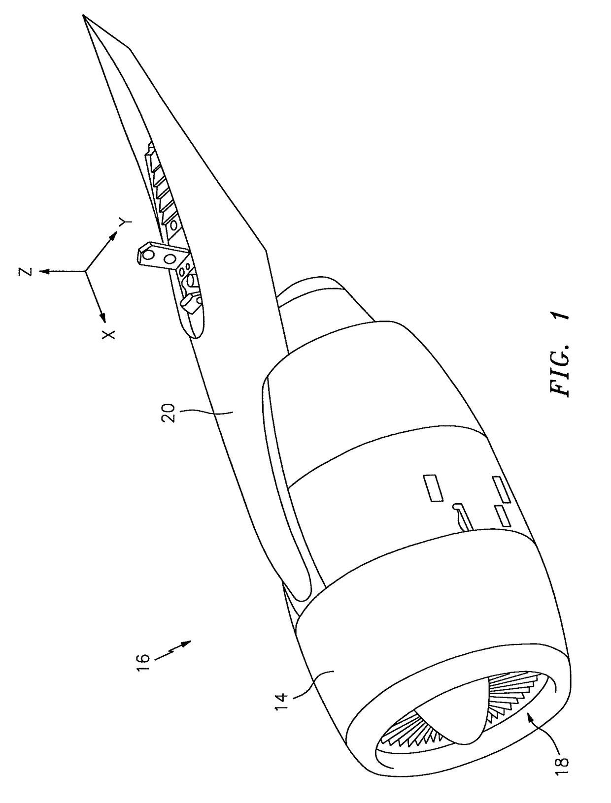
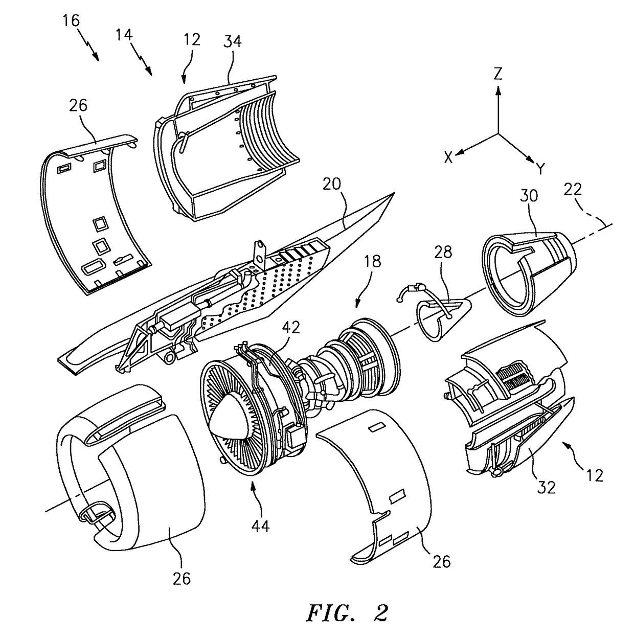
[0028]The present disclosure describes embodiments of a lower bifurcation wall aft edge portion aerodynamic feature 10 (hereinafter the “aerodynamic feature 10”) (see FIGS. 7-10), and embodiments of a thrust reverser 12 (see FIGS. 2-5) that includes the aerodynamic feature 10.

[0029]The present disclosure describes aspects of the present invention with reference to the exemplary embodiments illustrated in the drawings; however, aspects of the present invention are not limited to the exemplary embodiments illustrated in the drawings. The present disclosure may describe one or more features as having a length extending relative to an x-axis, a width extending relative to a y-axis, and / or a height extending relative to a z-axis. The drawings illustrate the respective axes.

[0030]The present disclosure uses the terms “circumferential,”“annular,”“abut,” and variations thereof, to describe one or more features. The term “circumferential,” and variations thereof, are used herein to indicate ...


PUM


Abstract

A thrust reverser of a propulsion system nacelle is provided. The thrust reverser includes a fixed structure, a translating structure, and an aerodynamic feature. The fixed structure includes an annular wall that partially defines an annular bypass airstream duct. The fixed structure is bifurcated into left and right side sections. The annular wall extends between upper and lower bifurcation walls of the left side section, and extends between upper and lower bifurcation walls of the right side section. The translating structure is moveable relative to the fixed structure, between a stowed position and a deployed position. The aerodynamic feature that includes a flange disposed relative to an aft end portion of one of the lower bifurcation walls. The flange aids in preventing aerodynamic drag.

Description

BACKGROUND[0001]1. Technical Field[0002]Aspects of the present invention relate to a thrust reverser of a propulsion system nacelle, and more particularly relate to an aerodynamic feature for aft edge portions of a thrust reverser lower bifurcation wall.[0003]2. Background Information[0004]It is known to provide a propulsion system that includes an engine (e.g., a gas turbine engine), a nacelle that at least partially surrounds the engine, and a pylon that connects the engine and the nacelle to a vehicle (e.g., an aircraft). In some instances, the thrust reverser includes a fixed structure and a translating structure that at least partially define an annular bypass airstream duct. The fixed structure includes a radially outer fixed structure and a radially inner fixed structure. The outer fixed structure includes an annular cascade array. The inner fixed structure includes an annular wall having a wall outer surface and a wall inner surface. The wall outer surface partially defines ...

Claims


Application Information

Patent Timeline
Patent Type & Authority Patents(United States)
IPC IPC(8): F02K1/72F02K1/56F02K1/78
CPCF02K1/566F02K1/78F02K1/72
Inventor BYRNE, STUART J.
Owner ROHR INC
Learn More