
Summer bypass for heat recovery ventilation units

A heat recovery, bypass channel technology, used in heat recovery systems, space heating and ventilation, space heating and ventilation details, etc., can solve problems such as heat exchangers

Active Publication Date: 2019-04-23
GREENWOOD AIR MANAGEMENT
View PDF6 Cites 0 Cited by
  • Summary
  • Abstract
  • Description
  • Claims
  • Application Information

AI Technical Summary

Problems solved by technology

But because the heat exchanger is not 100% effective, the temperature inside the room will gradually rise to match the outside temperature

Method used


Image

  • Summer bypass for heat recovery ventilation units
  • Summer bypass for heat recovery ventilation units
  • Summer bypass for heat recovery ventilation units

Examples


Embodiment Construction

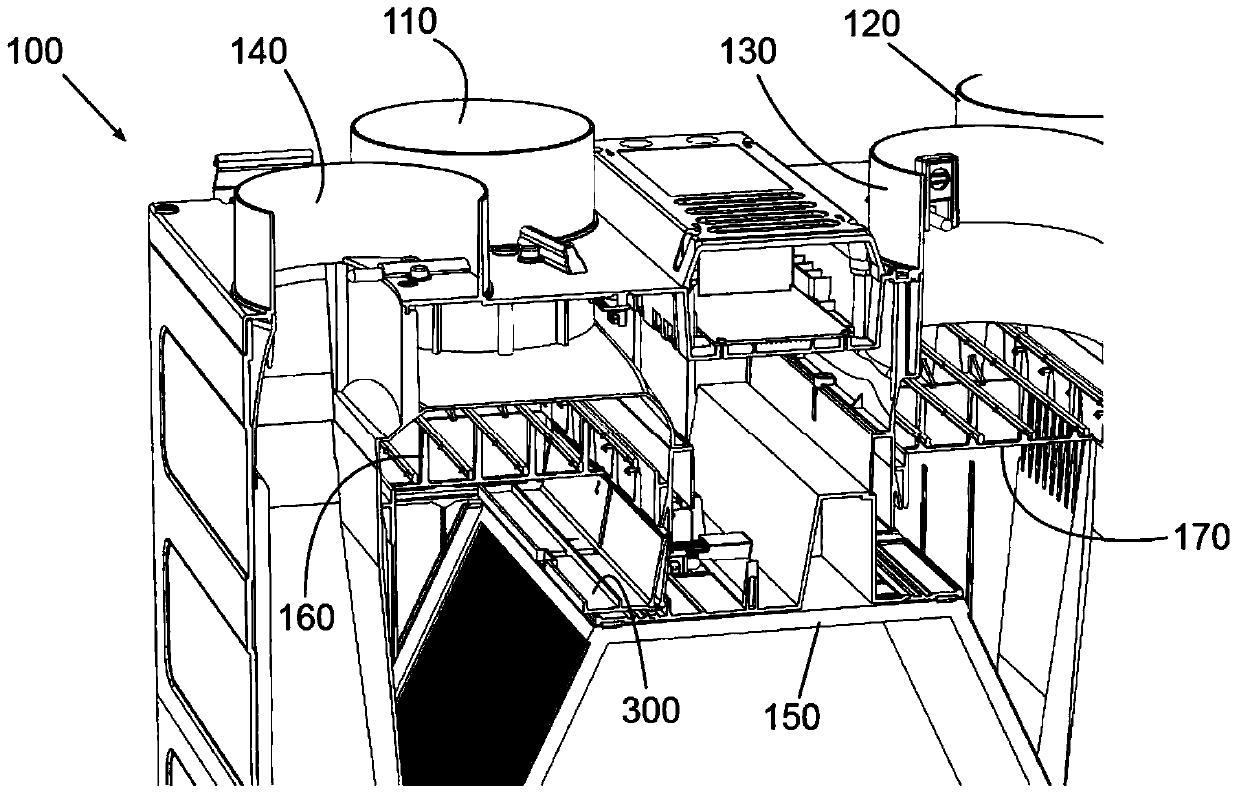
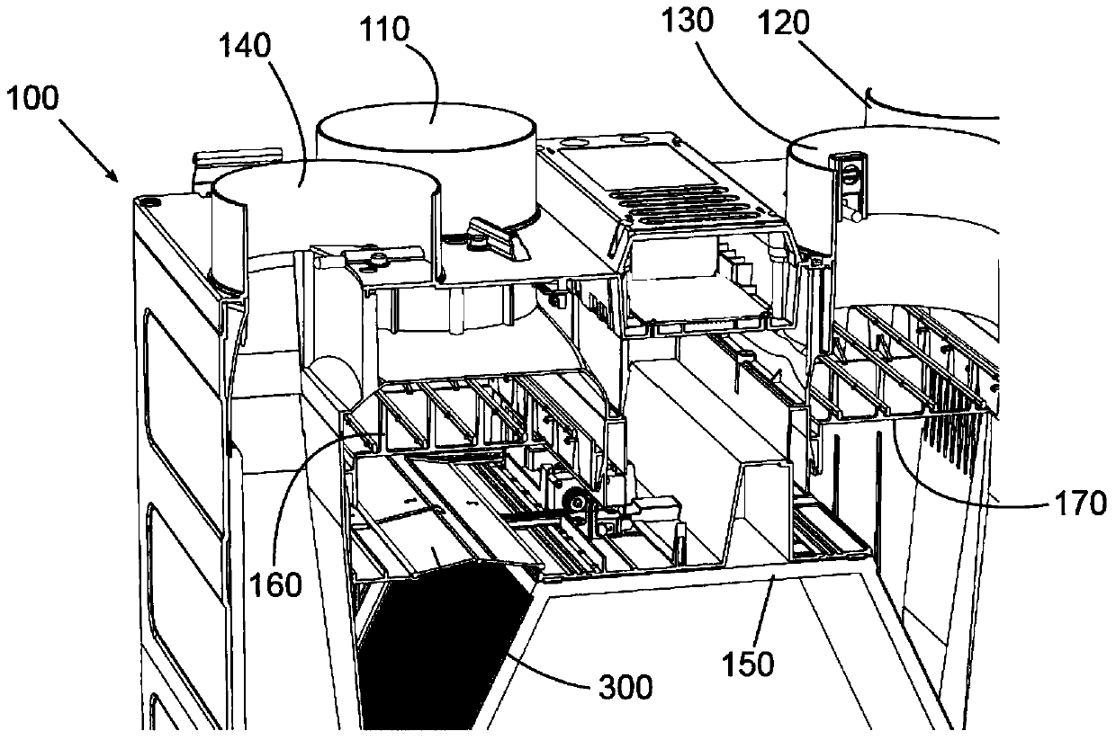
[0044] Figure 1a The first embodiment of the invention is shown. The first embodiment is a smaller heat recovery unit designed to be installed in a kitchen cabinet. The unit size is approximately 560mm by 550mm by 300mm.

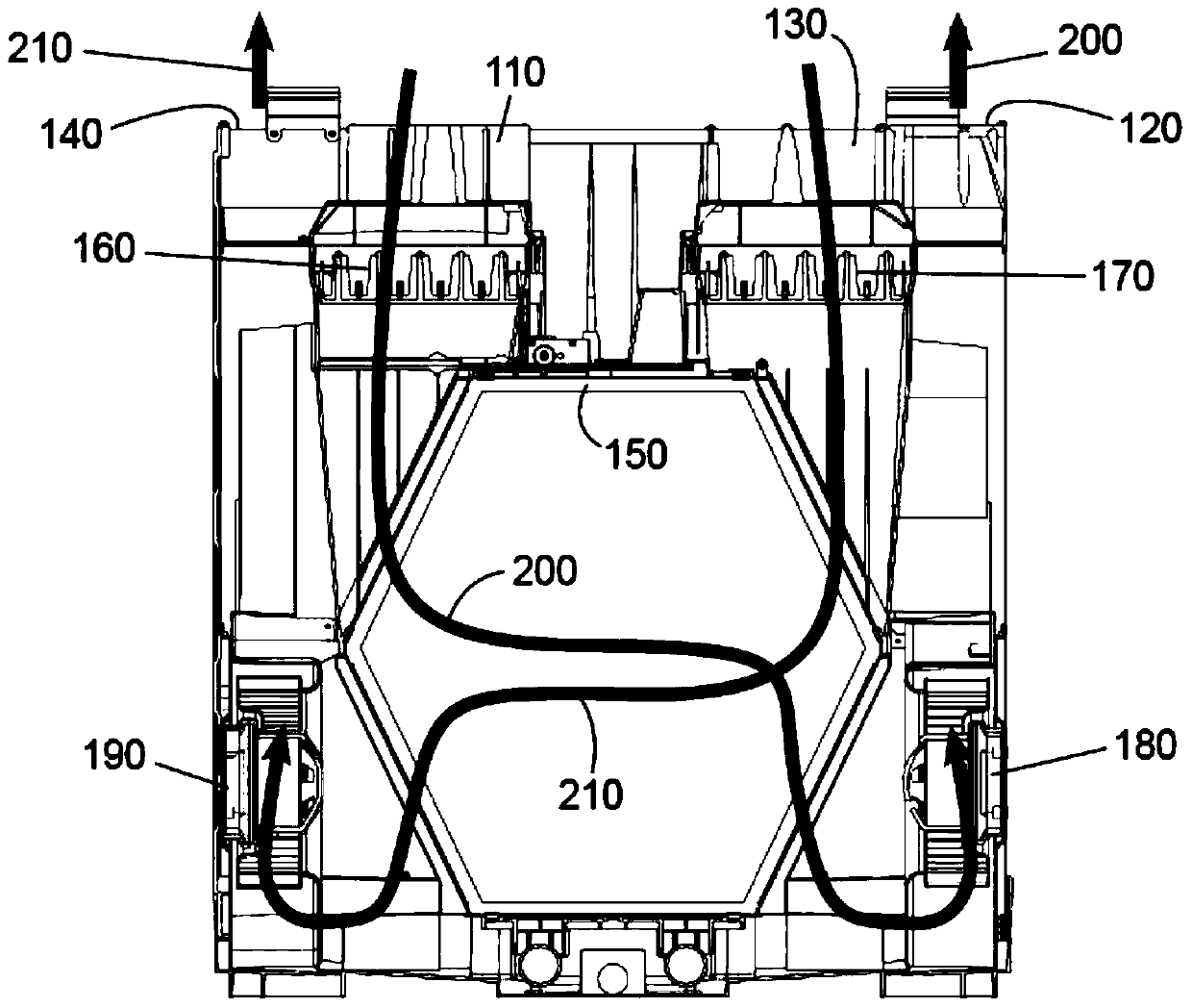
[0045] The heat recovery unit 100 has the following two inlets and two outlets: a first inlet 110, a first outlet 120, a second inlet 130, and a second outlet 140. Located below the first inlet 110 is the first filter 160. Located below the second inlet 130 is a second filter 170. In the middle of the unit is a heat exchanger 150.

[0046] In normal operation such as Figure 1a As shown, the first air flow path first passes through the first inlet 110, then through the heat exchanger 150, and then through the first centrifugal fan 180 ( Figure 1a (Not shown in the middle), then pass the first exit 120.

[0047] The second air flow path passes through the second inlet 130, then through the heat exchanger 150, and then through the second centrifugal fan 190 ( Figu...


PUM


Abstract

There is provided a heat recovery ventilation unit comprising a first air flow path and a second air flow path and a heat exchanger in which the first air flow path is in heat exchange contact with the second air flow path; the unit further comprising an air flow path selector in the first air flow path which is arranged to select between the first air flow path and a third air flow path which bypasses the heat exchanger; wherein the air flow path selector is located between an inlet filter of the first air flow path and the heat exchanger. Providing the bypass selector between the filter and the heat exchanger, air is always filtered, even in the bypass mode, thus reducing particulate matter drawn into the building during bypass operation.

Description

Technical field [0001] The invention relates to a heat exchanger or heat recovery unit used in a ventilation system. The present invention particularly relates to the summer bypass device for this heat recovery unit. Background technique [0002] In many technologies, heat exchangers are used to transfer heat between two fluids. The invention particularly relates to gas heat exchangers, in which heat exchange takes place between two different gas streams. [0003] The ventilation system can be balanced or unbalanced. In an unbalanced system, air is drawn from the building (usually in certain areas of the building, such as kitchens and toilets) and exhausted to remove excess moisture and / or odors. This system relies on the flow of air entering through natural openings such as windows or vents under doors to naturally replace the extracted air. This system has been used well in buildings with poor airtightness in the past, because those buildings have enough natural openings to a...

Claims


Application Information

Patent Timeline
IPC IPC(8): F24F12/00F24F13/12F24F13/16
CPCF24F12/006F24F13/12F24F13/16F24F2012/007Y02B30/56F24F1/0059F24F13/28F24F13/30F24F8/10
Inventor D·拜恩G·佛拉克D·拉西米M·贝勒
Owner GREENWOOD AIR MANAGEMENT
Learn More