
Piston type generator

A generator and piston-type technology, applied in the direction of machines/engines, electromechanical devices, electrical components, etc., can solve problems such as fuel waste

Pending Publication Date: 2018-09-07
彭继朕
View PDF4 Cites 0 Cited by
  • Summary
  • Abstract
  • Description
  • Claims
  • Application Information

AI Technical Summary

Problems solved by technology

[0006] In view of this, the object of the present invention is to provide a piston generator whose structural design can effectively solve the problem of wasteful fuel

Method used


Image

  • Piston type generator

Examples


Embodiment Construction

[0031] The object of the present invention is to provide a piston generator whose structural design can effectively solve the problem of waste of fuel.

[0032] The following will clearly and completely describe the technical solutions in the embodiments of the present invention with reference to the accompanying drawings in the embodiments of the present invention. Obviously, the described embodiments are only some, not all, embodiments of the present invention. Based on the embodiments of the present invention, all other embodiments obtained by persons of ordinary skill in the art without making creative efforts belong to the protection scope of the present invention.

[0033] In the description of the present invention, it should be understood that the orientation or positional relationship indicated by the terms "upper", "lower", "front", "rear", "left" and "right" are based on those shown in the accompanying drawings. Orientation or positional relationship is only for the...


PUM


Abstract

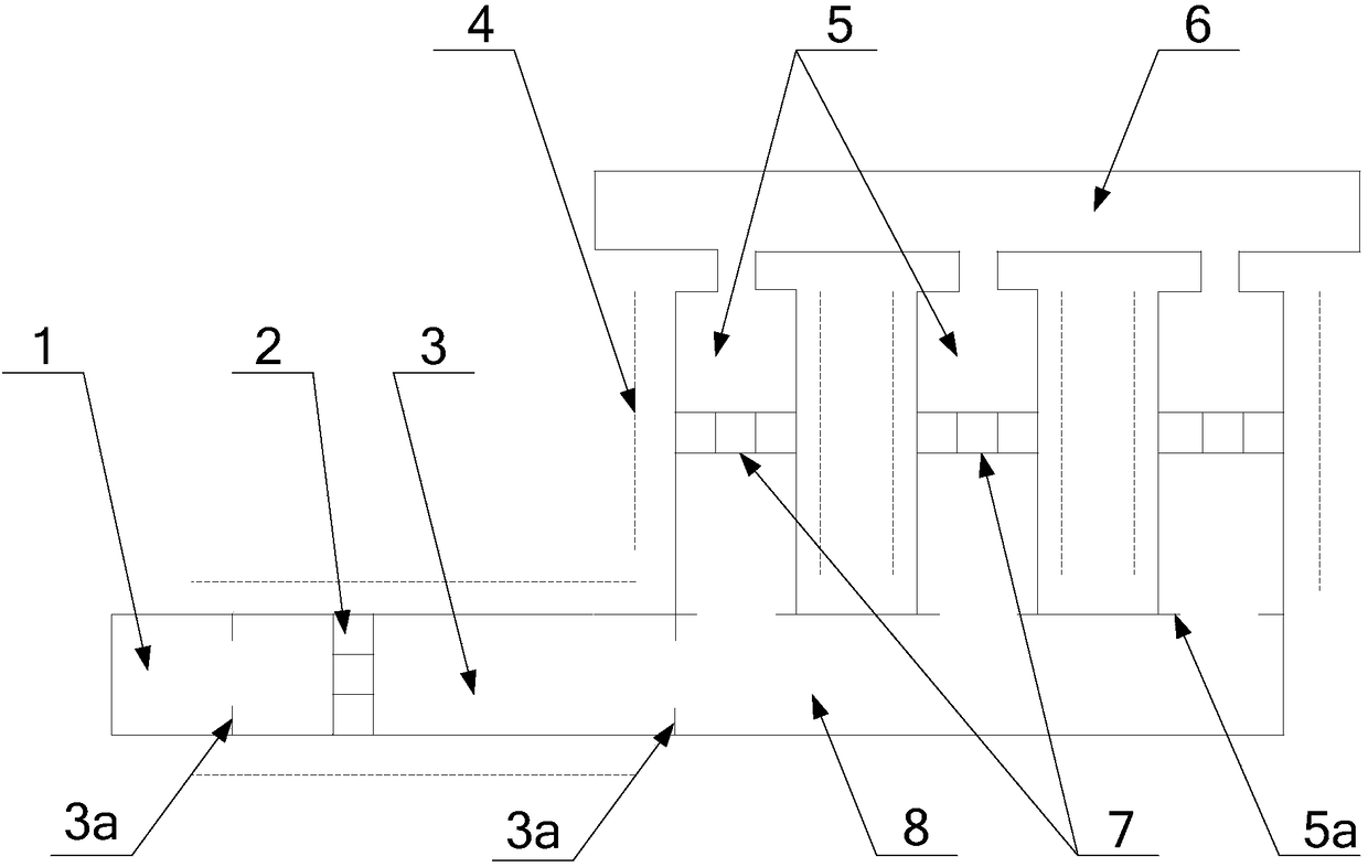
The invention discloses a piston type generator. The piston type generator comprises a combustion chamber, a first sliding way, a first piston, second sliding ways, second pistons and a vacuum cavity.The first end of the first sliding way communicates with the combustion chamber. The first piston is arranged in the first sliding way and separates the first end and the second end of the first sliding way. The first ends of the second sliding ways communicate with the second end of the first sliding way, and an included angle exists between the extending direction of each second sliding way andthe horizontal plane. The second pistons are arranged in the second sliding ways and separate the first ends and the second ends of the second sliding ways. Magnetic fields are arranged in the firstsliding way and / or the second sliding ways. The second ends of the second sliding ways communicate with the vacuum cavity. By means of structural design of the piston type generator, the problem thatfuel is wasted can be effectively solved.

Description

technical field [0001] The present invention relates to the technical field of generators, more specifically, to a piston generator. Background technique [0002] As a new type of serial hybrid power generation system, the free-piston linear power generation system has received extensive attention from many scientific research institutions at home and abroad in the past ten years. The device is directly coupled with a free-piston internal combustion engine and a linear generator. The combustion chamber expands to perform work, and the gas spring recovers after storing energy, driving the linear generator to reciprocate to generate electricity. [0003] The free-piston linear power generation system includes a combustion chamber, a piston, a coil and a gas spring. When the fuel in the combustion chamber is burned, the gas expands to push the piston to move. The piston moves to cut the magnetic lines generated by the coil to generate electricity. The piston moves while compres...

Claims


Application Information

Patent Timeline
IPC IPC(8): F02B63/04H02K35/02
CPCH02K35/02F02B63/041
Inventor 彭继朕
Owner 彭继朕
Learn More