
Discharging device and method for condensate water of steam heat exchanger

A discharge device and condensed water technology, applied in steam/steam condensers, chemical instruments and methods, transportation and packaging, etc., can solve problems such as reduced service life of steam heat exchangers, cracks, and poor drainage of condensed water

Pending Publication Date: 2022-06-24
CHINA PETROLEUM & CHEM CORP
View PDF0 Cites 0 Cited by
  • Summary
  • Abstract
  • Description
  • Claims
  • Application Information

AI Technical Summary

Problems solved by technology

[0002] Steam heat exchangers all need to discharge condensed water. At present, in order to make full use of low-temperature heat energy, condensed water is generally collected as a low-temperature heat source or reused as soft water. Therefore, corresponding Since there is no obvious height difference between the return water pipe and the position of the heat exchanger, or there is a height difference but the pipe diameter is insufficient, it is easy to cause poor drainage of condensed water, resulting in fluctuations in the heat transfer efficiency of the steam heat exchanger
[0003] In such a state of poor drainage, water will accumulate intermittently at the bottom of the steam heater, so that the bottom area of ​​the steam heat exchanger is always in a state of alternating contact with steam and condensed water, resulting in the plate at the bottom of the steam heat exchanger being frequently The state of expansion and contraction is prone to material fatigue aging, cracks, leakage, and further reducing the service life of the steam heat exchanger
In addition, since the condensed water is discharged from the steam heat exchanger in the state of a mixture of steam and water at the boiling point, it is easy to cause water hammer and erosion, reducing the service life of the pipeline
[0004] In addition, since the condensed water is discharged into the recycling pipeline and then decompressed, the condensed water at the saturation temperature will release steam, which will accumulate at the high point of the pipeline to form air resistance

Method used


Image

  • Discharging device and method for condensate water of steam heat exchanger
  • Discharging device and method for condensate water of steam heat exchanger

Examples


Embodiment Construction

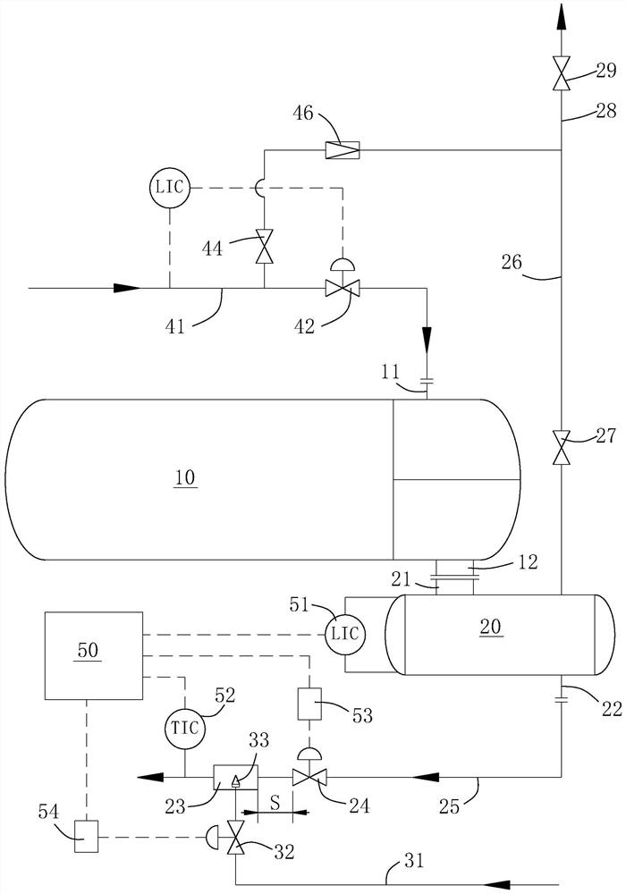
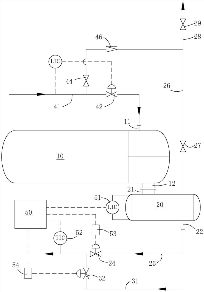
[0026] see figure 1 , a device for discharging condensed water of a steam heat exchanger, which comprises a condensed water tank 20 arranged below the steam heat exchanger 10, a condensed water discharge port 12 is arranged at the lower end of the steam heat exchanger 10, and the steam pipe 41 is connected to the On the steam inlet 11 at the top of the steam heat exchanger 10, a flow control valve 42 is installed on the steam pipe 41. In this embodiment, the steam heat exchanger 10 is used at the bottom of a distillation column or a fractionation column. Reboiler.

[0027] A water inlet 21 is provided on the top of the condensed water tank 20, the condensed water discharge port 12 is directly connected to the water inlet 21, the condensed water discharge port is located above the water inlet, and is not provided between the condensed water discharge port and the water inlet valve. It can be understood that, in another embodiment, when the installation space is limited, the c...


PUM


Abstract

The invention discloses a steam heat exchanger condensate water discharging device which comprises a condensate water tank arranged below a steam heat exchanger, a condensate water discharging opening is formed in the lower end of the steam heat exchanger, a water inlet is formed in the top of the condensate water tank, and the condensate water discharging opening is directly connected to the water inlet. Or the condensate water outlet is connected to the water inlet through a straight pipe; the bottom of the condensate water tank is connected with a drain pipe, and a demineralized water pipe is connected to the drain pipe; a drain valve is installed on the drain pipe, a water inlet valve is installed on the demineralized water pipe, and the connecting point of the demineralized water pipe and the drain pipe is located on the side, away from the condensate water tank, of the drain valve. The invention further discloses a condensate water discharging method adopting the discharging device. The heat exchange efficiency and the service life of the steam heat exchanger can be guaranteed.

Description

technical field [0001] The invention relates to a device for discharging condensed water of a steam heat exchanger and a method for discharging condensed water using the same. Background technique [0002] Steam heat exchangers all need to discharge condensed water. At present, in order to make full use of low-temperature heat energy, condensed water is generally collected as a low-temperature heat source or reused as soft water. Because there is no obvious height difference between the return water pipe and the heat exchanger, or there is a height difference but the pipe diameter is insufficient, it is easy to cause poor drainage of condensed water, resulting in fluctuations in the heat exchange efficiency of the steam heat exchanger . [0003] In such a state of poor drainage, water will accumulate at the bottom of the steam heater intermittently, so that the bottom area of ​​the steam heat exchanger is always in a state of alternating contact with steam and condensed wat...

Claims


Application Information

Patent Timeline
IPC IPC(8): F28B9/08F28B11/00F28F17/00F28F27/00B01F25/20
CPCF28B9/08F28B11/00F28F17/005F28F27/00
Inventor 刘文旭吴博枫陈明明张旭崔生旭
Owner CHINA PETROLEUM & CHEM CORP
Learn More