System for configuring a lighting device

a technology for lighting devices and systems, applied in the direction of electrical devices, etc., can solve the problems that the user's mobile device may not be able to (directly) communicate with the lighting device via one of these communication technologies, and the light switch may not be able to communicate with the lighting device via another communication technology

Active Publication Date: 2021-10-12
SIGNIFY HLDG BV
View PDF10 Cites 0 Cited by
  • Summary
  • Abstract
  • Description
  • Claims
  • Application Information

AI Technical Summary

Benefits of technology

[0007]It is an object of the present invention to reduce computing resources and / or network resources during the configuration of a lighting control device with a mobile device that uses a different communication technology than the lighting control device.
[0014]The lighting device comprises a memory, which is configured to store at least an association between the second light setting and the lighting control command. The processor is configured to store this association based on the received configuration command. The configuration command is received from a configuration device such as a smartphone, a tablet pc, a home control system, etc. After the processor has stored the association, the lighting device will be controlled according to the light setting associated with the unchanged lighting control command when the lighting control device (e.g. a light switch) is actuated by a user. Thus, from a user's perspective, it seems that the lighting control device has been reconfigured, while actually the lighting device has been reconfigured. Only configuring the lighting device is beneficial because it is no longer required to relay a configuration command from the configuration device—which is configured to communicate via a certain communication technology—to a lighting control device—which is configured to communicate via a different communication technology. Thus, computing resources at the switch device (and at a possible bridge device) are reduced during the configuration of the lighting control device. Also, a bridge device is no longer necessary. Additionally, network resources are reduced because less network traffic is required to configure how the lighting device responds to the lighting control device.
[0024]The second light setting may be a dynamic light setting. A dynamic light setting may be a light setting that changes its light output over time. The dynamic light setting may be a sequence of light settings that transition into each other over time. It is beneficial to store such a dynamic light setting in the memory of the lighting device, as this removes the need of transmitting the individual light settings to the lighting device over time.

Problems solved by technology

If a user would want to combine two systems that use different communication technologies, a user's mobile device may not be able to (directly) communicate with a lighting device via one of these communication technologies (e.g. ZigBee).
Additionally, a light switch may not be able to communicate with the lighting device via another communication technology (e.g. Bluetooth).

Method used


Image

  • System for configuring a lighting device
  • System for configuring a lighting device
  • System for configuring a lighting device

Examples


Embodiment Construction

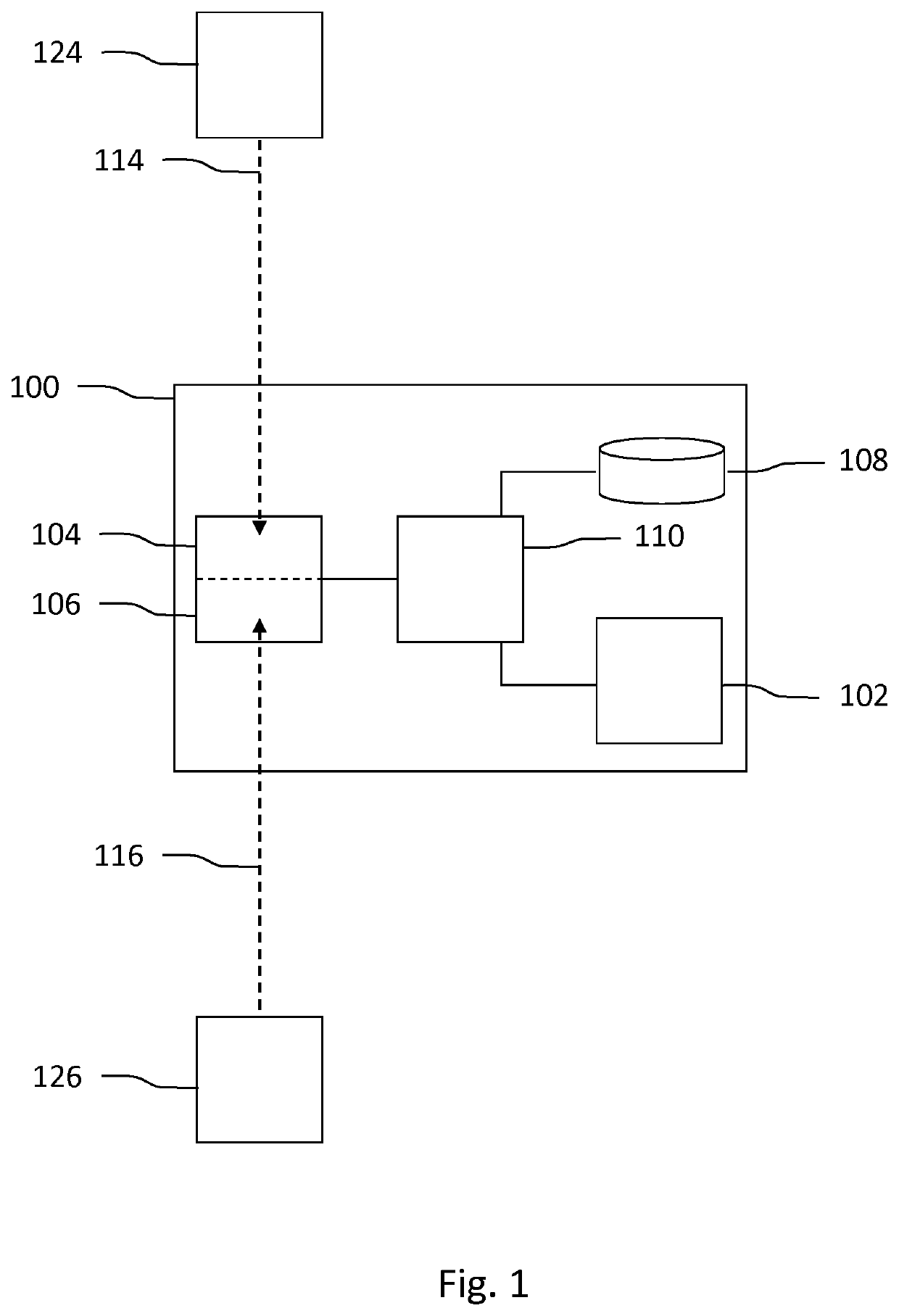
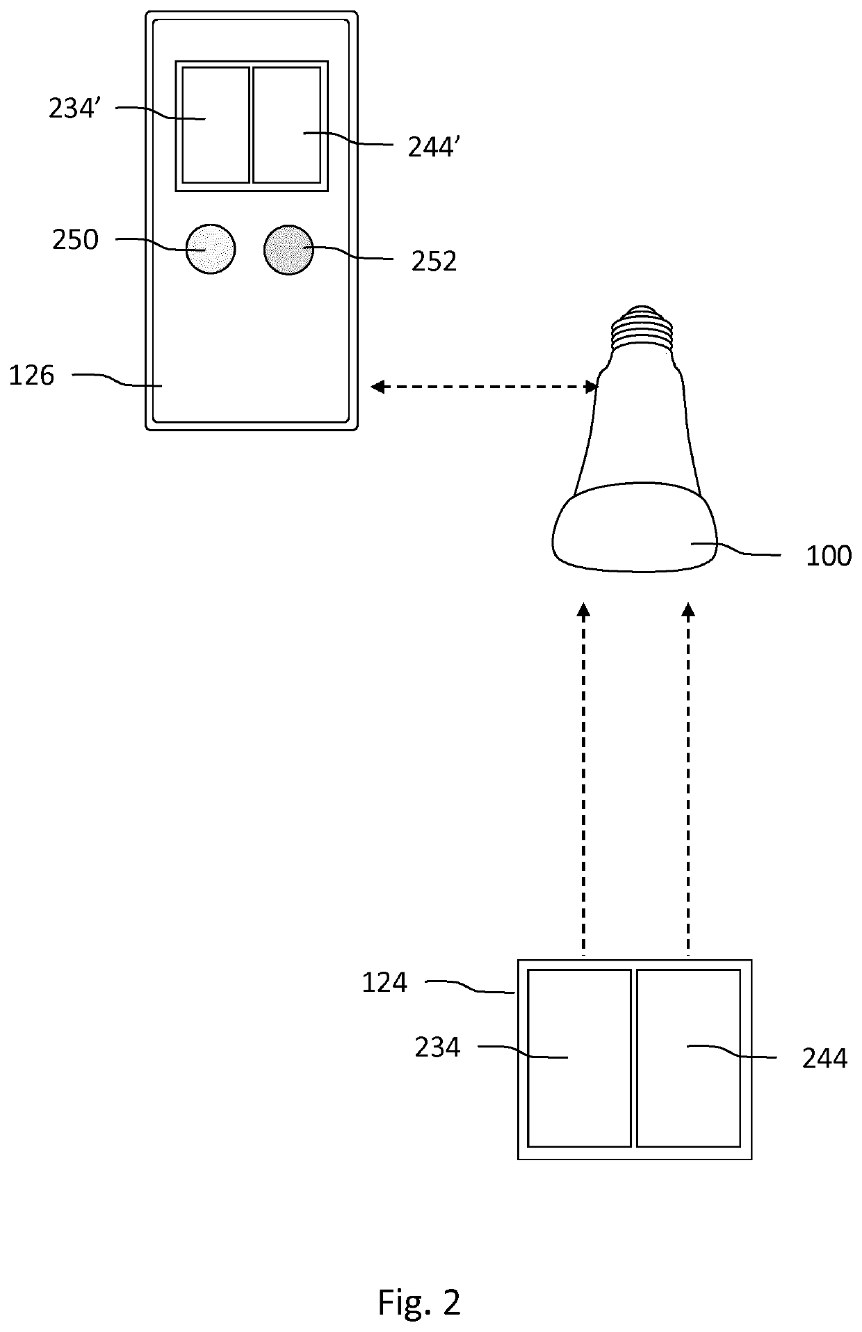
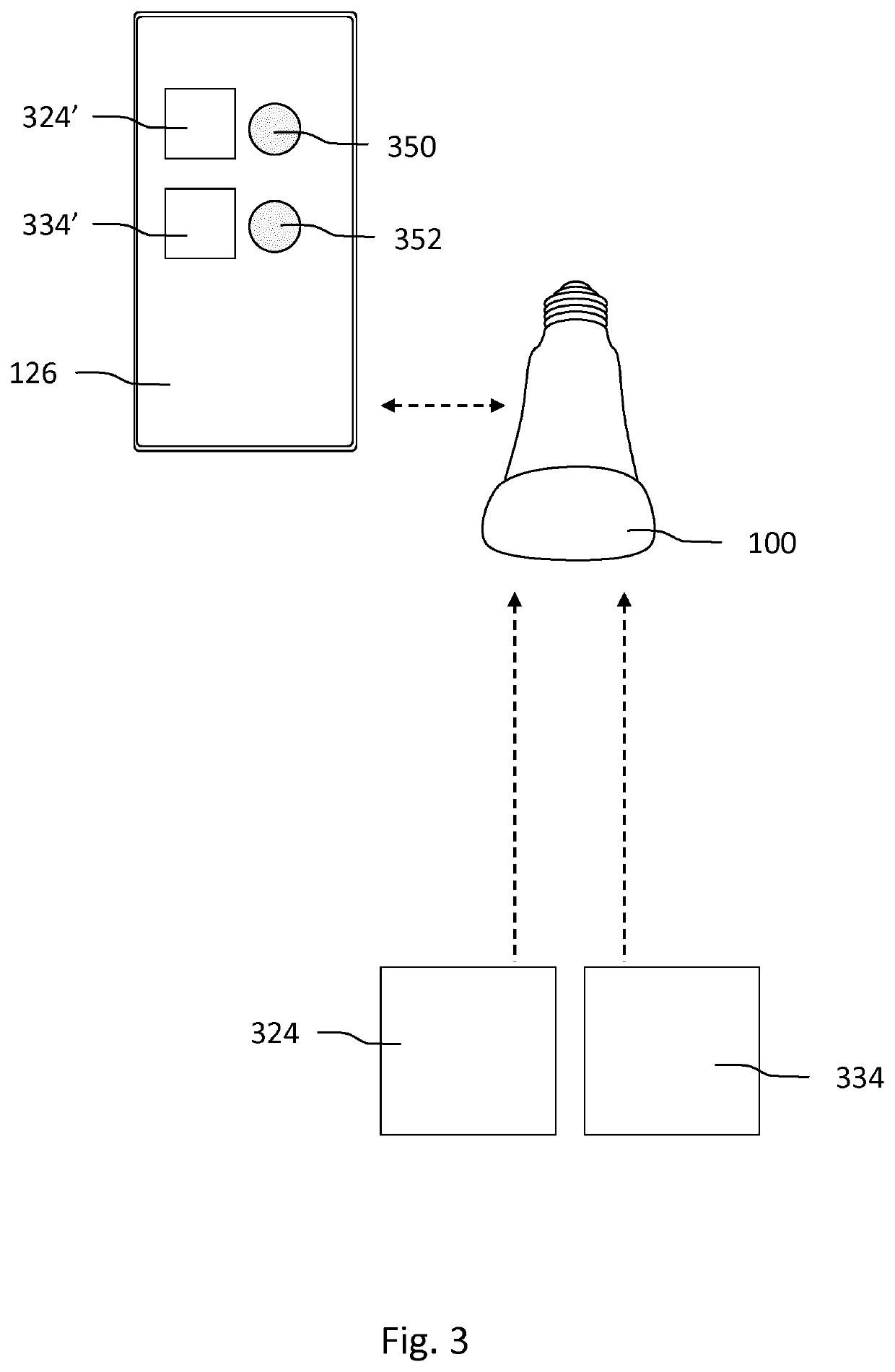
[0040]FIG. 1 shows schematically an embodiment of a system for configuring a lighting device 100. The system comprises the lighting device 100, a lighting control device 124 and a configuration device 126. In this system, the configuration device 126 is unable to communicate directly with the lighting control device 124, as the lighting control device 124 is configured to communicate via a first communication technology 114 that is not present in the configuration device 126. The lighting device 100 comprises a controllable (LED) light source. The lighting device 100 further comprises a first communication module 104 configured to communicate via a first wireless communication technology 114, and configured to receive a lighting control command from the lighting control device 124 via the first wireless communication technology 114. The lighting device 100 further comprises a second communication module 106 configured to communicate via a second wireless communication technology 126...


PUM


Abstract

A lighting device (100) is disclosed. The lighting device (100) comprises a light source (102), a first communication module (104) configured to communicate via a first wireless communication technology, and configured to receive a lighting control command from a lighting control device via the first wireless communication technology, a second communication module (106) configured to communicate via a second wireless communication technology, and configured to receive a configuration command from a configuration device via the second wireless communication technology, wherein the configuration command comprises information related to a second light setting, a memory (108), a processor (110) configured to control the light source (102) according to a first light setting associated with the lighting control command upon receiving the lighting control command from the lighting control device, wherein the processor (110) is further configured to store an association between the second light setting and the lighting control command in the memory (108) upon receiving the configuration command, and wherein the processor (110) is further configured to control the light source (102) according to the second light setting upon receiving the same lighting control command after the association has been stored.

Description

CROSS-REFERENCE TO PRIOR APPLICATIONS[0001]This application is the U.S. National Phase application under 35 U.S.C. § 371 of International Application No. PCT / EP2019 / 065547, filed on Jun. 13, 2019, which claims the benefit of European Patent Application No. 18179776.2, filed on Jun. 26, 2018. These applications are hereby incorporated by reference herein.FIELD OF THE INVENTION[0002]The invention relates to a lighting device and to a system for configuring the lighting device. The invention further relates to a method of configuring a lighting device, and to a computer program product for executing the method.BACKGROUND[0003]Connected home and office lighting systems enable users to control the light output of lighting devices with their smartphones, light switches and other lighting control devices. Current systems often use a single communication technology, such as Bluetooth or ZigBee. In systems that use a point-to-point communication technology such as Bluetooth or Wi-Fi, lightin...

Claims


Application Information

Patent Timeline
Patent Type & Authority Patents(United States)
IPC IPC(8): H05B47/19
CPCH05B47/19
Inventor MEERBEEK, BERENT WILLEMMEKENKAMP, GERHARDUS ENGBERTUS
Owner SIGNIFY HLDG BV
Why Eureka
Try Eureka