Method for performing hybrid over-current protection detection in a display module, and associated timing controller

a display module and timing controller technology, applied in the field of fail detection, can solve the problems of over-current protection (ocp) failing to be triggered, display device abnormal display, etc., and achieve the effect of enhancing the fail detection mechanism, reducing the overall cost, and increasing the additional cos

Active Publication Date: 2021-11-09
HIMAX TECH LTD
View PDF2 Cites 0 Cited by
  • Summary
  • Abstract
  • Description
  • Claims
  • Application Information

AI Technical Summary

Benefits of technology

[0004]It is another objective of the present invention to provide a method for performing hybrid OCP detection in a display module, and to provide an associated timing controller, in order to enhance fail detection mechanism without introducing a side effect or in a way that less likely to introduce a side effect.
[0007]The present invention method and associated apparatus (e.g. the timing controller) can guarantee that sufficient information for correct judgment regarding whether the display side or the host side malfunctions is available. In addition, implementing the embodiments of the present invention does not significantly increase additional costs. Therefore, the related art problems can be solved, and the overall cost will not increase too much. In comparison with the related art, the present invention method and associated apparatus can enhance fail detection mechanism without introducing any side effect or in a way that is less likely to introduce a side effect.

Problems solved by technology

However, some problems may occur.
For example, when one or more signals input into the display device are erroneous (e.g. the pixel clock may be too fast), the display device may display abnormally, and more particularly, may consume a large current, causing an over-current protection (OCP) fail to be triggered.
As a result, there may be misjudgment regarding whether the display side or the host side malfunctions.

Method used


Image

  • Method for performing hybrid over-current protection detection in a display module, and associated timing controller
  • Method for performing hybrid over-current protection detection in a display module, and associated timing controller
  • Method for performing hybrid over-current protection detection in a display module, and associated timing controller

Examples


Embodiment Construction

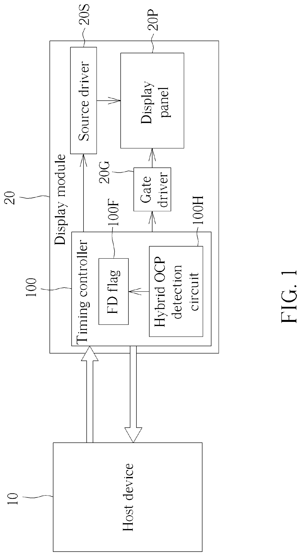
[0018]FIG. 1 is a diagram of a host system according to an embodiment of the present invention, where the host system may comprise a host device 10 and a display module 20, and the display module 20 may comprise a timing controller 100, at least one source driver (e.g. one or more source drivers) which may be collectively referred to as the source driver 20S, at least one gate driver (e.g. one or more gate drivers) which may be collectively referred to as the gate driver 20G, and a display panel 20P. For better comprehension, the host system shown in FIG. 1 may be implemented within an automotive vehicle such as a car, a bus, etc., and may be arranged to control operations of the automotive vehicle, where the display module 20 (e.g. the display panel 20P, etc. thereof) may represent a liquid crystal display (LCD) module (e.g. an LCD panel, etc. thereof) implemented according to LCD technologies, but the present invention is not limited thereto. For example, the display module 20 may...


PUM


Abstract

A method for performing hybrid over-current protection (OCP) detection in a display module and associated timing controller are provided. The method includes: during initialization of the display module, after a set of driving voltages have been established, performing first OCP detection in a built-in self-test (BIST) mode to generate a first OCP detection result; writing the first OCP detection result into a register bank, for being accessed by a host device, wherein the display module is applicable to displaying information for the host device; performing second OCP detection in a normal mode to generate a second OCP detection result; and writing the second OCP detection result into the register bank, for being accessed by the host device.

Description

BACKGROUND OF THE INVENTION1. Field of the Invention[0001]The present invention relates to fail detection, and more particularly, to a method for performing hybrid over-current protection (OCP) detection in a display module and an associated timing controller.2. Description of the Prior Art[0002]Built-in display devices such as liquid crystal display (LCD) panels have been widely used in automotive vehicles such as cars, buses, etc. According to the related art, a display device of a host system in a car may notify the host system of an error by changing (e.g. pulling up) a voltage level of a certain signal. However, some problems may occur. For example, when one or more signals input into the display device are erroneous (e.g. the pixel clock may be too fast), the display device may display abnormally, and more particularly, may consume a large current, causing an over-current protection (OCP) fail to be triggered. As a result, there may be misjudgment regarding whether the display...

Claims


Application Information

Patent Timeline
Patent Type & Authority Patents(United States)
IPC IPC(8): G09G3/00G09G3/36
CPCG09G3/006G09G3/3696G09G2310/08G09G2330/04G09G2330/12G06F3/147
Inventor CHEN, CHING-LUN
Owner HIMAX TECH LTD
Why Eureka
Try Eureka