Marine propulsion system

a propulsion system and marine technology, applied in marine propulsion, propulsive elements, vessel construction, etc., can solve problems such as the failure of the shift position switching mechanism while maneuvering a vessel

Active Publication Date: 2009-08-27
YAMAHA MOTOR CO LTD
View PDF3 Cites 14 Cited by
  • Summary
  • Abstract
  • Description
  • Claims
  • Application Information

AI Technical Summary

Benefits of technology

[0006]In order to overcome the problems described above, preferred embodiments of the present invention provide a marine propulsion system which compensates for a shift position switching mechanism failure.

Problems solved by technology

However, with the marine propulsion system described in JP-A-2006-264361, a shift position switching mechanism may fail while maneuvering a vessel.

Method used


Image

  • Marine propulsion system
  • Marine propulsion system
  • Marine propulsion system

Examples


Embodiment Construction

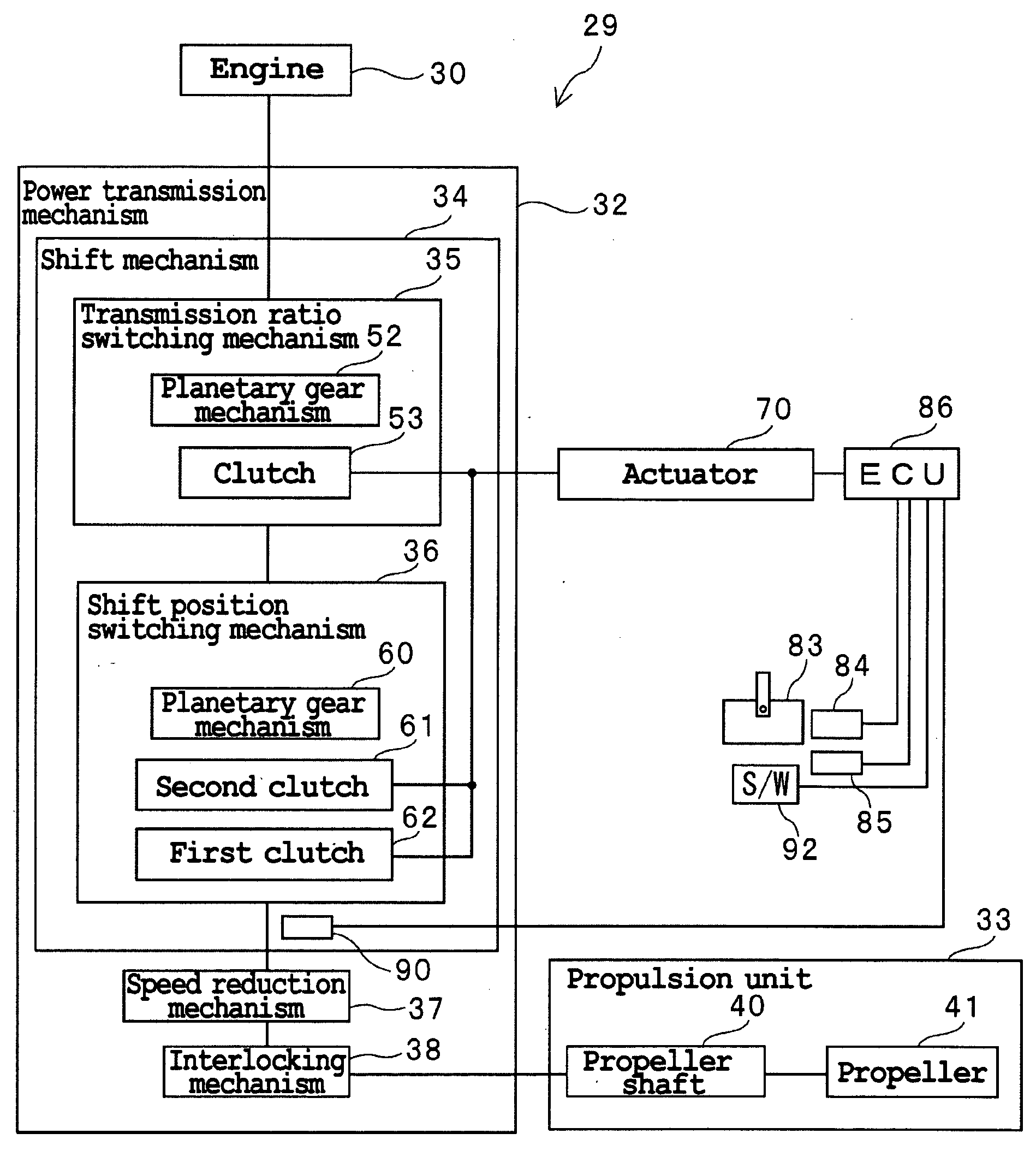
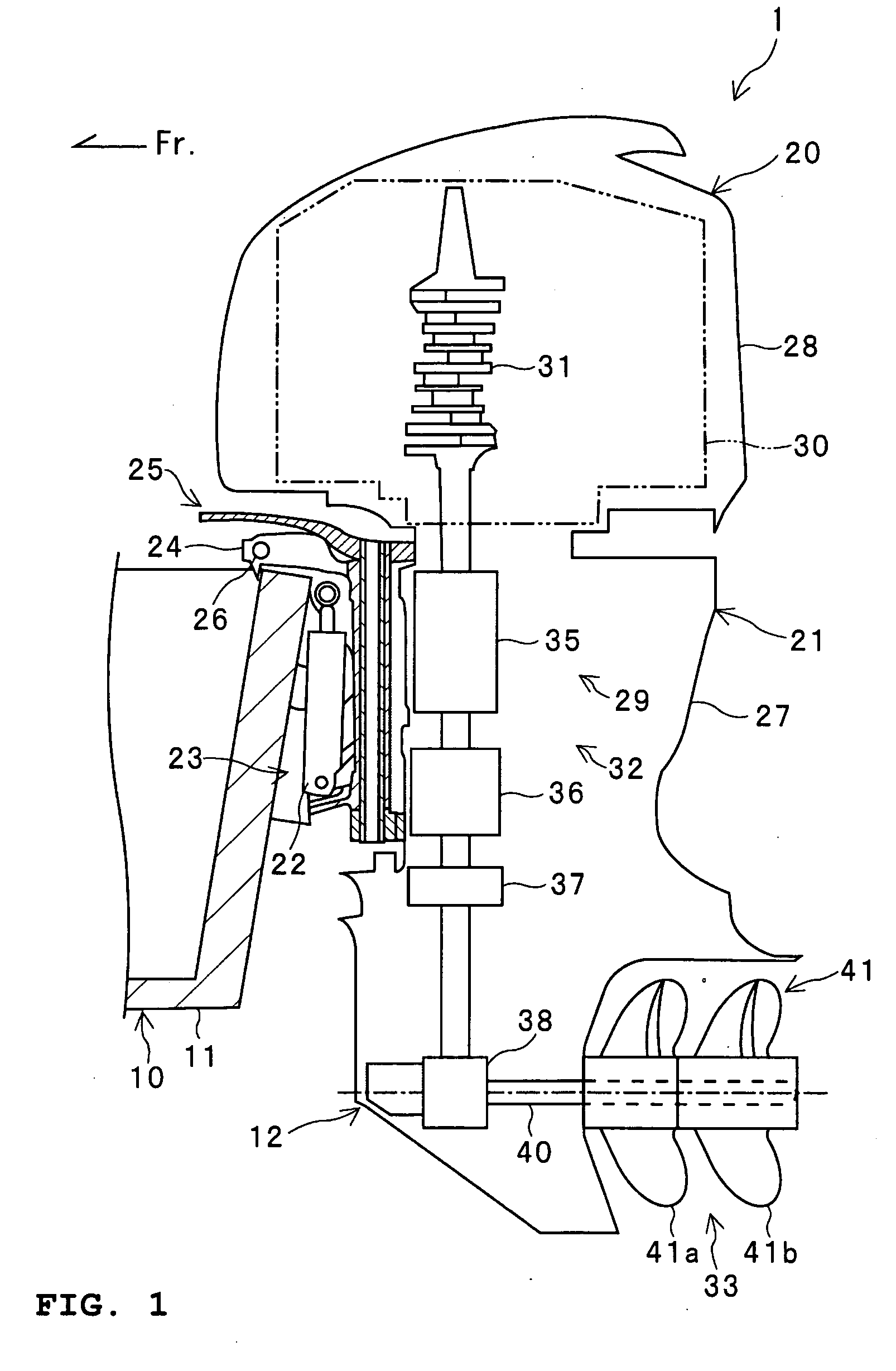
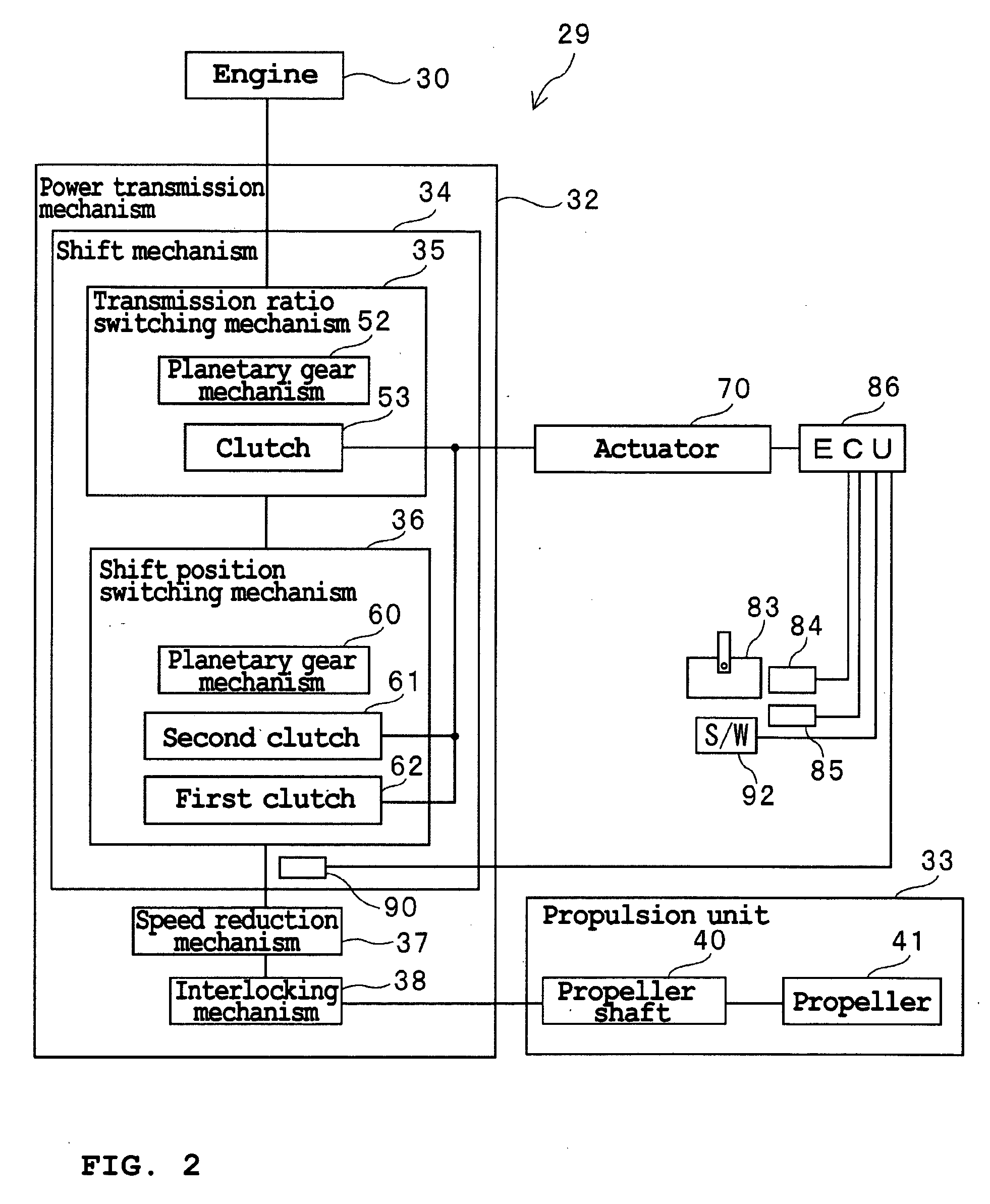
[0052]Description is hereinafter made of a preferred embodiment of the present invention using an outboard motor 20 shown in FIG. 1 as a marine propulsion system. It should be noted that the following preferred embodiment is merely an example of one preferred form of the present invention. The present invention is not limited to the following preferred embodiment.

[0053]A marine propulsion system according to a preferred embodiment of the present invention may be what is called an inboard motor or what is called a stern drive. Stern drives are also called “inboard-outboard motors.” A “stern drive” is a marine propulsion system at least the power source of which is mounted on a hull. “Stern drives” include engines also having components mounted on a hull other than the propulsion unit.

[0054]FIG. 1 is a schematic partial cross-sectional view, as seen from a side, of a portion of the stern 11 of a vessel 1 according to the present preferred embodiment. As shown in FIG. 1, the vessel 1 h...


PUM


Abstract

A marine propulsion system includes an outboard motor including an engine, a propeller, a shift position switching mechanism, an oil pump, valves, and an ECU. The shift position switching mechanism includes hydraulic clutches arranged to change the connection state between the engine and the propeller. The shift position switching mechanism is switchable among forward, reverse, and neutral. A first valve opens and closes the communication between the oil pump and a first hydraulic clutch. A second valve opens and closes the communication between the oil pump and a second hydraulic clutch. A third valve opens and closes the communication between the oil pump and each of third and fourth valves.

Description

BACKGROUND OF THE INVENTION[0001]1. Field of the Invention[0002]The present invention relates to a marine propulsion system.[0003]2. Description of the Related Art[0004]A technique for switching the shift position of an outboard motor by driving a shift position switching mechanism of the outboard motor with an electric actuator has been suggested as described in, for example, JP-A-2006-264361. The shift position switching mechanism described in JP-A-2006-264361 is disposed in what is called a shell-shaped portion in which a propeller shaft is disposed. The shift position switching mechanism has a dog clutch for shift position switching. In the shift position switching mechanism described in JP-A-2006-264361, the dog clutch is engaged or disengaged with the electric actuator to achieve a shift position change among forward, reverse, and neutral.[0005]However, with the marine propulsion system described in JP-A-2006-264361, a shift position switching mechanism may fail while maneuver...

Claims


Application Information

Patent Timeline
Patent Type & Authority Applications(United States)
IPC IPC(8): B63H21/21B63H20/00B63H23/30F16H61/12
CPCB63H20/14B63H21/21B63H23/30B63H23/08B63H21/213B63H23/18B63H2021/205Y02T70/5236
Inventor SUZUKI, TAKAYOSHINAKAMURA, DAISUKE
Owner YAMAHA MOTOR CO LTD
Why Eureka
Try Eureka