Method and system for alignment of wire contact with wire contact insertion holes of a connector

a wire contact and insertion hole technology, applied in the direction of programme control, instruments, image enhancement, etc., can solve the problems of increasing the overall assembly cost including the wire bundle assembly, limiting the flexibility with which the wire bundle may be presented, and not being suitable, so as to facilitate the automated insertion and reduce the cost associated with the resulting assembly. , the effect of reducing the error rate of the connection

Active Publication Date: 2021-11-09
THE BOEING CO
View PDF19 Cites 1 Cited by
  • Summary
  • Abstract
  • Description
  • Claims
  • Application Information

AI Technical Summary

Benefits of technology

[0004]A method, system and computer program product are provided for aligning wire contacts with insertion holes defined by a connector so as to facilitate the automated insertion of the wire ends of a wire bundle assembly into the wire contact insertion holes of a connector. By facilitating the automated insertion of the wire ends of a wire bundle assembly into the wire contact insertion holes of a connector, the time required to establish such connections and correspondingly the cost associated with the resulting assembly may be reduced while reducing the error rate associated with the connections. The method, system and computer program product of an example embodiment provide substantial flexibility in relation to the manner in which the connector may be located, while still permitting the wire ends of a wire bundle assembly to be securely inserted into and electrically connected to the appropriate wire contact insertion holes of the connector.
[0005]In an example embodiment, a system is provided to align wire contacts with insertion holes of a connector. The system may include a robot having an end-effector, where the end-effector includes a wire gripper and at least two image capture devices secured to the end-effector; and a computing device. The computing device may be configured to: obtain captured images from the at least two image capture devices; detect, within at least one image from each of the at least two image capture devices, a wire contact; detect, within at least one image from each of the at least two image capture devices, one or more insertion holes of the connector; identify corrective movement for the robot end-effector that aligns a target hole of the one or more insertion holes of the connector with the wire connector; and cause the robot to move the end-effector according to the identified corrective movement. The computing device configured to detect, within at least one image from each of the at least two image capture devices, a wire contact, may be further configured to detect a location of the wire contact and a direction of the wire contact along which the wire contact extends.
[0008]Embodiments described herein may provide a method for aligning wire contacts with insertion holes of a connector. Methods may include: obtaining captured images from at least two image capture devices attached to an end-effector of a robot of a wire gripper of the end-effector; detecting, within at least one image from each of the at least two image capture devices, a wire contact; detecting, within at least one image from each of the at least two image capture devices, one or more insertion holes of the connector; identifying corrective movement for the robot end-effector that aligns a target hole of the one or more insertion holes of the connector with the wire connector; and causing the robot to move the end-effector according to the identified corrective movement. Detecting, within at least one image from each of the at least two image capture devices, a wire contact, may include detecting a location of the wire contact and a direction of the wire contact along which the wire contact extends.

Problems solved by technology

As wire bundle assemblies commonly include hundreds of wires, this manual connection process may be relatively time consuming and error prone and, as a result, may increase the cost of the overall assembly including the wire bundle assembly.
However, wire bundle assembly machines generally require the connectors to be in a very restricted and controlled set of locations in order to increase the likelihood that the wire ends of the wire bundle assembly may be properly inserted into the wire contact insertion holes of the connector.
As such, wire bundle assembly machines limit the flexibility with which connectors may be presented and, as such, are not suitable for all scenarios.

Method used


Image

  • Method and system for alignment of wire contact with wire contact insertion holes of a connector
  • Method and system for alignment of wire contact with wire contact insertion holes of a connector
  • Method and system for alignment of wire contact with wire contact insertion holes of a connector

Examples


Embodiment Construction

[0028]The present disclosure now will be described more fully hereinafter with reference to the accompanying drawings, in which some, but not all aspects are shown. Indeed, the disclosure may be embodied in many different forms and should not be construed as limited to the aspects set forth herein. Rather, these aspects are provided so that this disclosure will satisfy applicable legal requirements. Like numbers refer to like elements throughout.

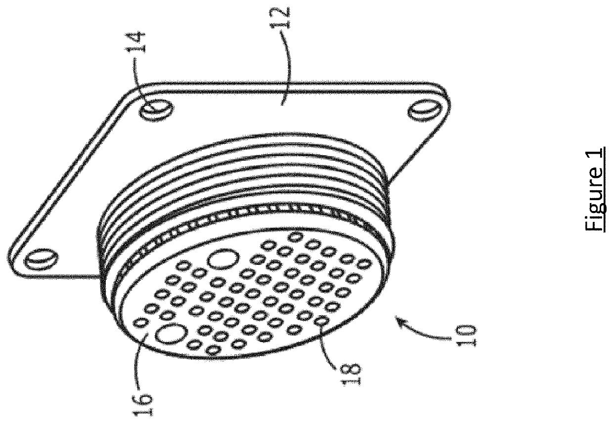
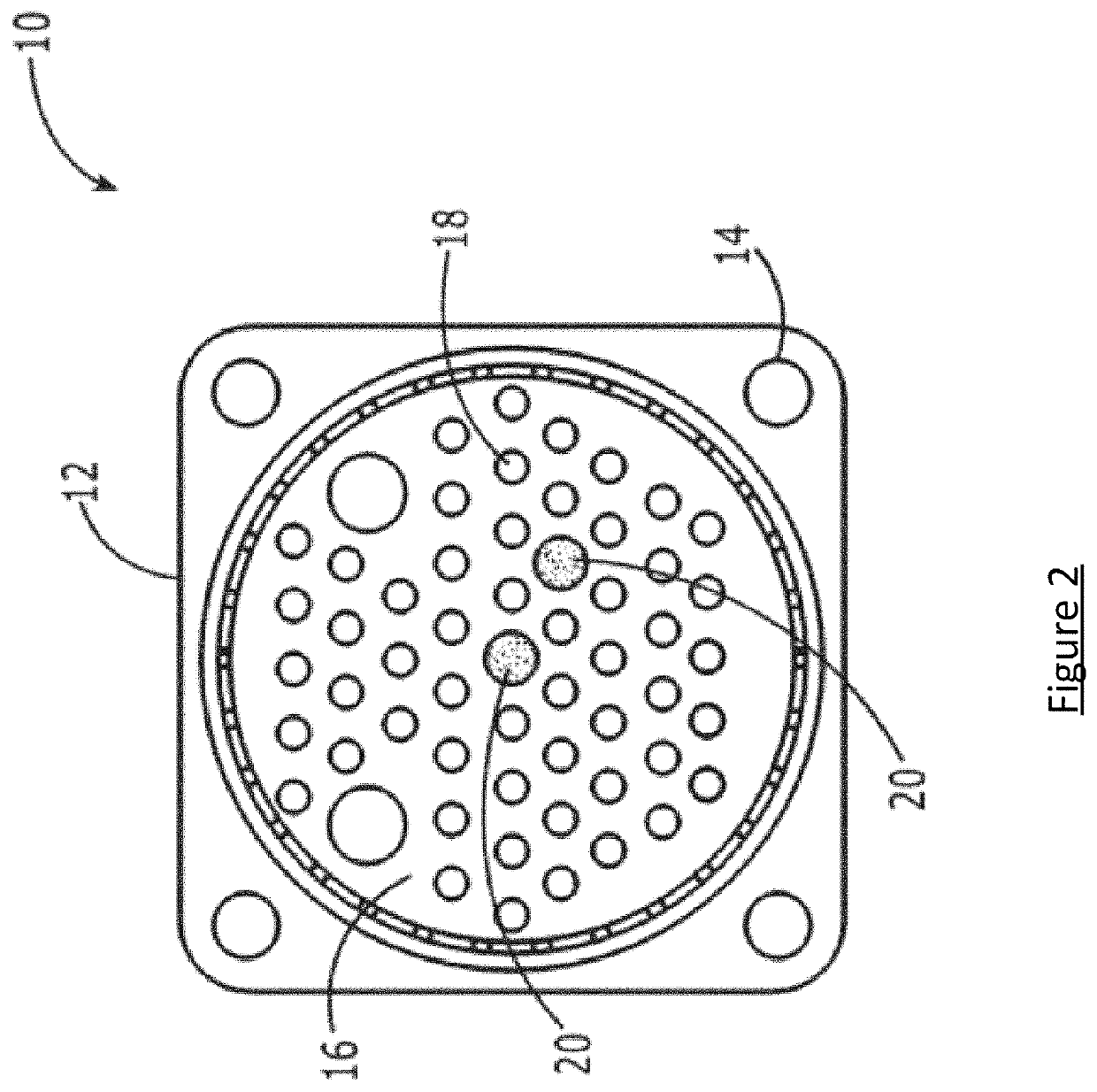
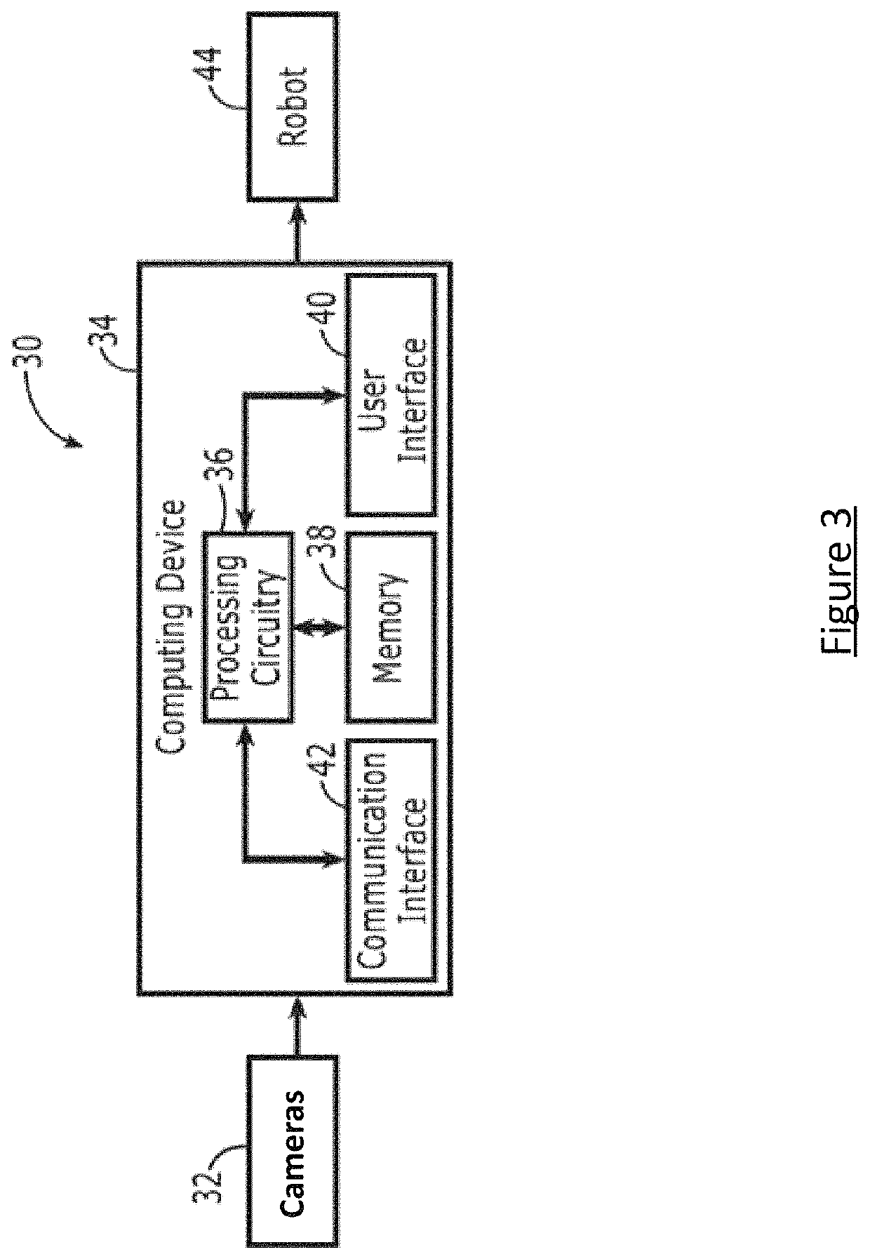
[0029]A method, system, and computer program product are provided in accordance with an example embodiment described herein to align wire ends / contacts with corresponding insertion holes of a connector, such as in a rubber grommet of a connector, to facilitate automatic robotic wire insertion. The process described herein detects wire contact and insertion holes simultaneously using robotic-end-effector-mounted cameras. Using simultaneous detection, embodiments of the disclosed method provide feedback for corrective movements of a robot arm ...


PUM


Abstract

A method, system and computer program product are provided for aligning wire contacts with wire contact insertion holes of a connector to facilitate the automated insertion of the wire ends of a wire bundle assembly into the wire contact insertion holes of a connector. Methods may include: obtaining captured images from at least two image capture devices attached to an end-effector of a robot of a wire gripper of the end-effector; detecting, within at least one image from each of the at least two image capture devices, a wire contact; detecting, within at least one image from each of the at least two image capture devices, one or more insertion holes of the connector; identifying corrective movement for the robot end-effector that aligns a target hole of the one or more insertion holes of the connector with the wire connector; and causing the robot to move the end-effector according to the identified corrective movement.

Description

TECHNICAL FIELD[0001]A method, system and computer program product are provided in accordance with an example embodiment in order to align wire contacts with insertion holes of a connector, and more particularly, to using a machine-vision system to automatically align wire contacts with wire contact insertion holes of a connector.BACKGROUND[0002]Wire bundles consisting of a plurality of wires are utilized in a variety of industries to carry a myriad of different types of signals. The wire of a wire bundle assembly must frequently be terminated with a wire contact and the resulting wire end is inserted into a wire contact insertion hole of a connector, such as in a rubber grommet of a connector. As each wire of a wire bundle is unique and may carry a different type of signal, the wire ends of a wire bundle assembly must be inserted into specific wire contact insertion holes of a connector in order to make the proper connections.[0003]The wire ends of a wire bundle assembly may be man...

Claims


Application Information

Patent Timeline
Patent Type & Authority Patents(United States)
IPC IPC(8): H01R43/20G06T7/73G06T7/13B25J9/16G06T7/00G06V10/48
CPCH01R43/20B25J9/1687B25J9/1697G06T7/001G06T7/13G06T7/73G06T2207/10024G06T7/70G06T7/90G06T2207/30108G06T2207/10004G06V10/751G06T2207/30152G06T2207/20061G06T7/593G06T2207/10012B25J15/00B25J13/08B25J19/023G05B2219/40032G05B2219/39045G06V20/10G06V10/48
Inventor HOFFMANN, HEIKO
Owner THE BOEING CO
Why Eureka
Try Eureka