Supercharge Your Innovation With Domain-Expert AI Agents!

Fence clip apparatus and method

a technology of fencing and clipping, applied in fencing, building types, constructions, etc., can solve the problems of difficult separation and use, inefficient, time-consuming,

Active Publication Date: 2021-11-16
BULLET FENCE SYST LLC
View PDF48 Cites 0 Cited by
  • Summary
  • Abstract
  • Description
  • Claims
  • Application Information

AI Technical Summary

Benefits of technology

The present invention is an apparatus for attaching fence wire on a T-post. It includes several components: a body assembly, a slide plate, an upper plate, a V-clip, and a bending lever. Additionally, the apparatus also includes wire grasping hooks on the body assembly, which have an L-shaped design. The invention provides a solution that simplifies the process of attaching fence wire to a T-post and reduces the need for manual labor.

Problems solved by technology

Heretofore, when constructing such fences, it has been necessary to carry a pouch or package of loose, partially bent wire clips which become tangled and are difficult to separate and use.
This process is very tedious, inefficient, and time consuming.

Method used


Image

  • Fence clip apparatus and method
  • Fence clip apparatus and method
  • Fence clip apparatus and method

Examples


Embodiment Construction

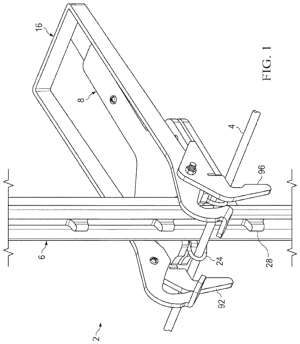
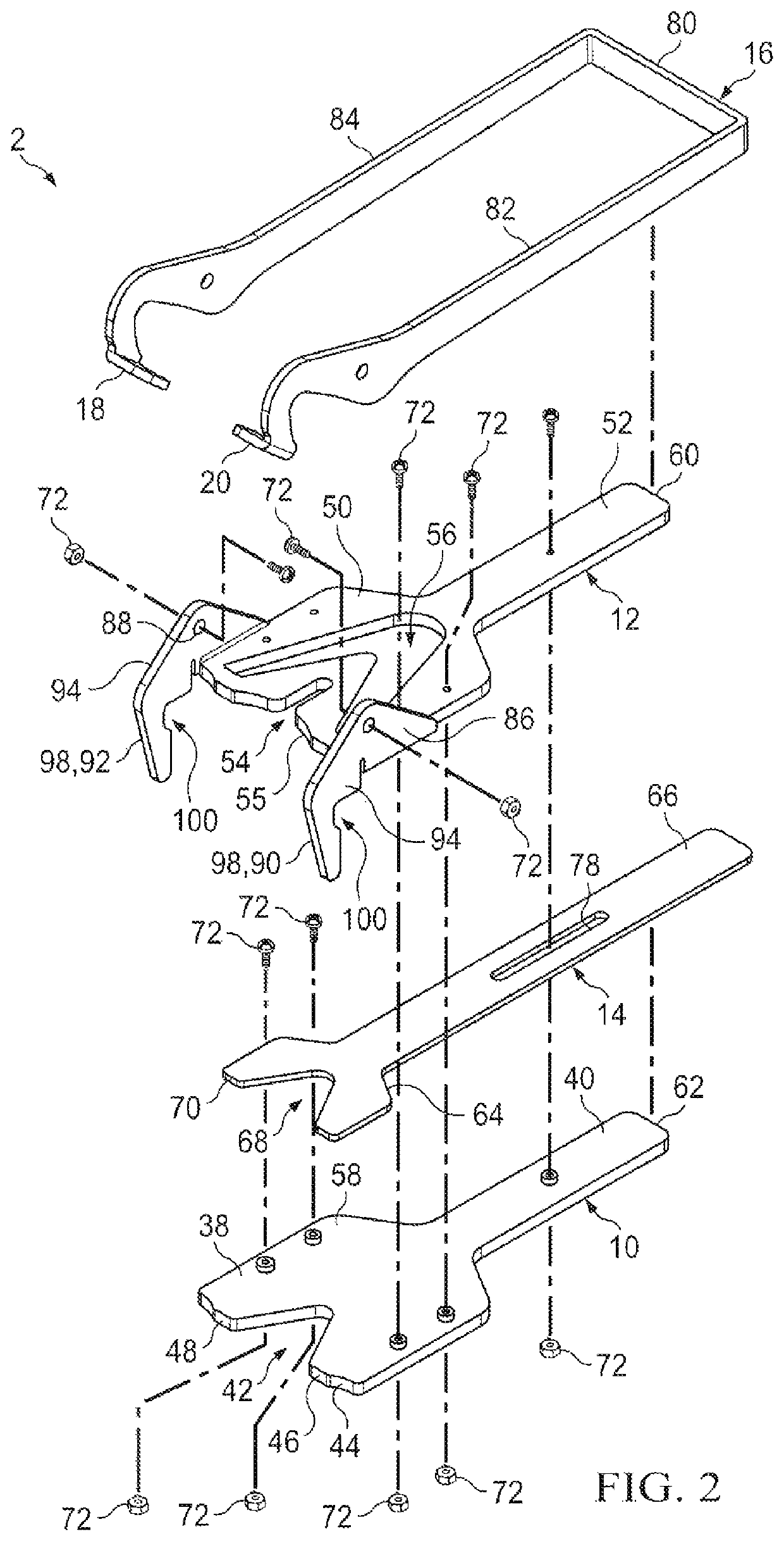
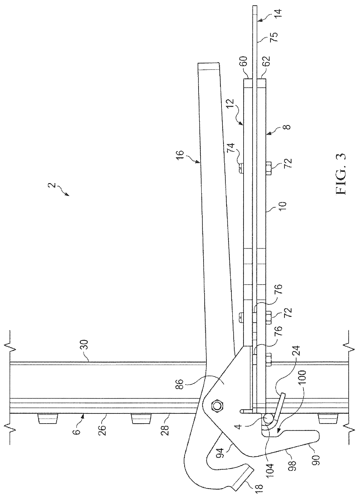
[0018]An embodiment 2 of the inventive apparatus for clipping a fence wire 4 on an upwardly extending T-post 6 is shown in FIGS. 1-5. The inventive clipping apparatus 2 preferably comprises: (i) a body assembly 8 comprising a lower plate 10, an upper plate 12 positioned above the lower plate 10, and a slide plate 14 which is slideably retained between the lower plate 10 and the upper plate 12 for forward and rearward sliding movement; (ii) a clip bending lever 16 which is pivotably positioned on the body assembly 8 and includes left and right forward clip-contacting structures 18 and 20; (iii) a V-clip feed magazine 22 which is removably positionable on the body assembly 8; and (iv) a supply (i.e., a vertical stack) of flat V-clips 24 in the V-clip magazine 22.

[0019]Although other types of posts could alternatively be used, a common type of T-post 6 to which the fence wire 4 will be attached will typically have a cross-sectional T shape as illustrated in FIGS. 3 and 4 comprising: (a...


PUM


Abstract

An apparatus and method for clipping a fence wire on a T-post.

Description

RELATED CASE[0001]This application claims the benefit of U.S. Provisional Patent Application Ser. No. 62 / 816,342 filed on Mar. 11, 2019 and incorporates said provisional application by reference into this document as if fully set out at this point.FIELD OF THE INVENTION[0002]The present invention relates to apparatuses and methods for attaching fence wires to fence posts.BACKGROUND OF THE INVENTION[0003]Wire fences formed of one or more, typically at least two, lengths of fence wire attached to a series of vertical metal T-posts are commonly used in the livestock industry and for other purposes. Heretofore, when constructing such fences, it has been necessary to carry a pouch or package of loose, partially bent wire clips which become tangled and are difficult to separate and use. In addition, when connecting the horizontal fence wires to the T-posts, it has been necessary for the worker to lift each wire to its required elevation on the post, place a preformed clip around the back ...

Claims


Application Information

Patent Timeline
IPC IPC(8): E04H17/10E04H17/26
CPCE04H17/10E04H17/268E04H17/124
Inventor GOEDECKE, RONALD D.
Owner BULLET FENCE SYST LLC
Features
  • R&D
  • Intellectual Property
  • Life Sciences
  • Materials
  • Tech Scout
  • Unparalleled Data Quality
  • Higher Quality Content
  • 60% Fewer Hallucinations
Learn More