Supercharge Your Innovation With Domain-Expert AI Agents!

Polarization converter based on taking high-order TE mode as transition mode

a converter and high-order technology, applied in the field of polarization converters, can solve the problems of reduced bandwidth, small tolerance of devices, and inability to ensure yield, and achieve the effects of low yield, high design difficulty, and high demands on machining precision

Active Publication Date: 2021-12-07
WUHAN POST & TELECOMM RES INST CO LTD
View PDF3 Cites 0 Cited by
  • Summary
  • Abstract
  • Description
  • Claims
  • Application Information

AI Technical Summary

Benefits of technology

[0006]It is an object of the present invention to solve the problems of high demands on machining precision, great difficulty in design and low yields existing in the prior polarization converters, and the present invention provides a polarization converter based on taking a high-order TE mode as a transition mode.
[0018]The present invention has the following beneficial effects: the polarization converter of the present invention, which is based on taking a high-order TE mode as a transition mode, employs the ridge waveguide and the slab waveguide, which are arranged in double layers, to achieve the high-efficiency conversion between the TM0 mode and the TE1 mode; then, the strip waveguide which is symmetric or asymmetric in width and varying in width is employed to achieve the high-efficiency conversion between the high-order TE mode and the TE0 mode, thereby finally achieving the high-efficiency conversion between TM0 and TE0 polarization states; the technological complexity is low, the tolerance is large, and the yield is high.

Problems solved by technology

1. The making of L-shaped waveguides, which directly achieve conversion between the TM0 mode and the TE0 mode, has extremely high demands on the precision of alignment machining; consequently, such devices are small in tolerance, and the yield can't be ensured;
2. As for inverted T-shaped waveguides connected with an asymmetric MZI, as devices are large in number, the designing work is inevitably faced with greater difficulties, and meanwhile, the connection of multiple devices will produce additional insertion losses and lead to reduction in bandwidth; as for inverted T-shaped waveguides connected with a directional coupler, as the directional coupler would be sensitive to band gaps between two waveguides, demands on machining precision are also high, and the yield is low.

Method used


Image

  • Polarization converter based on taking high-order TE mode as transition mode
  • Polarization converter based on taking high-order TE mode as transition mode

Examples


Embodiment Construction

[0022]In order to provide a better understanding of the present invention, the contents of the present invention will be further illustrated below in combination with embodiments, but they should not be limited only to the embodiments illustrated below. Various changes or modifications may be made to the present invention by those skilled in the art, and these equivalents also fall within the range as defined by the claims listed in the present application.

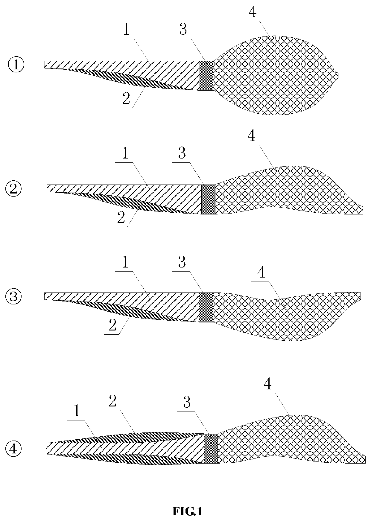
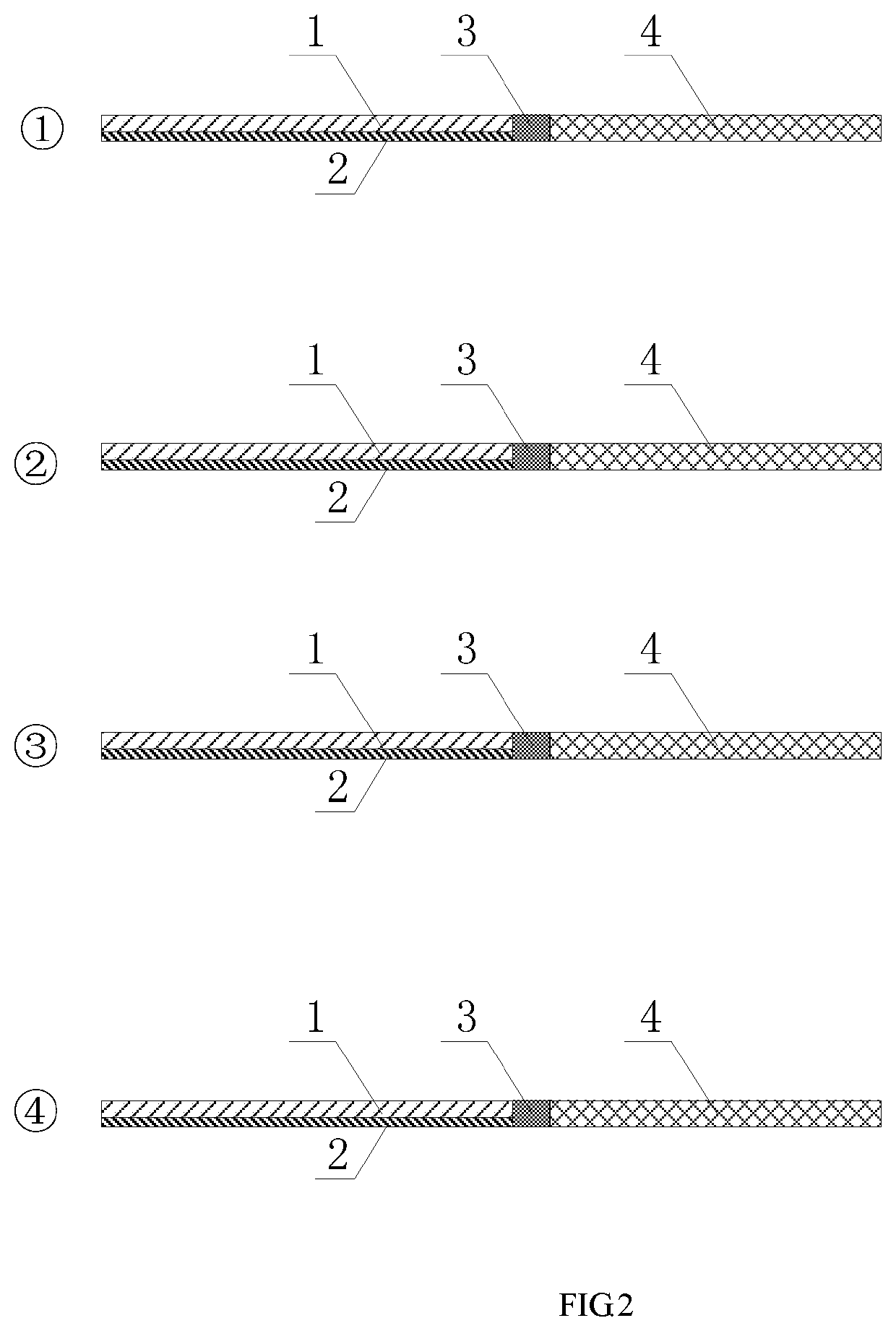
[0023]As shown in FIG. 1, the present invention provides a polarization converter based on taking a high-order TE mode as a transition mode, wherein the polarization converter taking a high-order even-order TE mode as a transition mode comprises a ridge waveguide 1 and a slab waveguide 2 which are arranged in double layers, asymmetric in width and tapering in width, a strip waveguide 4 which is symmetric or asymmetric in width and varying in width, and a transition section waveguide 3 for connecting together the ridge waveguide 1,...


PUM


Abstract

A polarization converter based on taking a high-order TE mode as a transition mode comprises a ridge waveguide (1) and a slab waveguide (2) that are arranged in double layers and varying in width, and a strip waveguide (4) which is varying in width. The ridge waveguide (1) is disposed on the upper end face of the slab waveguide (2), and is aligned with two ends of the slab waveguide (2). The right end of the ridge waveguide (1) and the slab waveguide (2) are connected with the strip waveguide (4) with the varying width. A TM0 mode enters from the left ends of the ridge waveguide and the slab waveguide, and is converted into a TE0 mode for output. On the contrary, the TE0 mode enters from the right end of the strip waveguide and is converted into the TM0 mode for output.

Description

FIELD OF THE INVENTION[0001]The present invention relates to a polarization converter, and more particularly, to a polarization converter based on taking a high-order TE mode as a transition mode.BACKGROUND OF THE INVENTION[0002]The polarization converter is an important device for polarization division multiplexing in optical communication. Currently used polarization converters may be generalized into two kinds: polarization converters of the first kind employ waveguides having a cross-section resembling an “L” shape or similar shapes to achieve direct conversion between the TM0 mode and the TE0 mode; polarization converters of the second kind employ inverted T-shaped waveguides to achieve conversion between the TM0 mode and the TE1 mode, and then, the TE1 mode is converted into the TE0 mode using an asymmetric Mach-Zehnder interferometer (MZI) or a directional coupler. Currently, there are the following problems:[0003]1. The making of L-shaped waveguides, which directly achieve c...

Claims


Application Information

Patent Timeline
Patent Type & Authority Patents(United States)
IPC IPC(8): G02B6/14G02B27/28G02B6/12G02B6/27G02B6/126
CPCG02B6/14G02B6/126G02B6/12014G02B6/2766G02B27/28G02B27/286G02B6/274G02B2006/12097G02B2006/12147G02B2006/12152
Inventor CHEN, DAIGAOXIAO, XIWANG, LEIQIU, YINGLI, MIAOFENGLIU, LEIYANG, QIYU, SHAOHUA
Owner WUHAN POST & TELECOMM RES INST CO LTD
Features
  • R&D
  • Intellectual Property
  • Life Sciences
  • Materials
  • Tech Scout
  • Unparalleled Data Quality
  • Higher Quality Content
  • 60% Fewer Hallucinations
Learn More