
Load sensing devices for use in surgical instruments

a technology for sensing devices and surgical instruments, applied in the field of load sensing devices for use in surgical instruments, can solve the problems of increasing the thickness of the strain gauge, the overall electrical signal, and the potential failure point, so as to reduce the resistance change, reduce and limit the effect of averaging

Active Publication Date: 2021-12-14
COVIDIEN LP
View PDF506 Cites 0 Cited by
  • Summary
  • Abstract
  • Description
  • Claims
  • Application Information

AI Technical Summary

Benefits of technology

[0008]Conventional strain gauges may have a constant gauge factor, or a constant change in resistance for a given strain. Thus, by changing the overall shape of the conductive traces on the strain gauge a different signal response can be generated. The present disclosure provides for strain gauges that span the length of the jaw members, such that when the I-beam of the loading unit travels longitudinally through the jaw members to clamp, staple, and cut tissue there is an active region of the strain gauge disposed distally of the actuation sled. As noted above, the problem is that as the actuation sled is moved longitudinally, the active portion of the strain gauge decreases, causing an averaging effect of the entire strain gauge, which lowers the resistance change and consequently, the overall electrical signal. Currently, conventional strain gauges have a constant gauge factor throughout. The present disclosure provides for strain gauges of various shapes and dimensions and in particular their conductive grids such that different areas of the strain gauge have different gauge factors, thereby limiting the effects of averaging.
[0009]The strain gauge according to the present disclosure may also be disposed on a flexible circuit. Conventional strain gauges require solder connections or wire bond in order to complete the circuit. This can cause potential failure points and also increases the thickness of the strain gauge which prevents its placement within the loading unit. The strain gauge according to the present disclosure may also includes signal, power, and ground leads, which are also disposed as traces on the flexible circuit. This allows for the placement of the strain gauge within the loading unit.
[0011]The strain gauge is formed by depositing the resistance material in a predetermined pattern in a first, e.g., proximal, portion, and an uninterrupted layer in a second, e.g. distal, portion. The predetermined pattern of the resistance material is masked and the conductive material traces are disposed directly over the uninterrupted layer of the resistance material. This configuration obviates the need for additional insulation layers, thereby minimizing the thickness of the strain gauge. Since the resistance material has a higher resistance than the conductive material, the current only flows through the conductive material that is disposed over the uninterrupted layer of the resistance material.

Problems solved by technology

As noted above, the problem is that as the actuation sled is moved longitudinally, the active portion of the strain gauge decreases, causing an averaging effect of the entire strain gauge, which lowers the resistance change and consequently, the overall electrical signal.
This can cause potential failure points and also increases the thickness of the strain gauge which prevents its placement within the loading unit.

Method used


Image

  • Load sensing devices for use in surgical instruments
  • Load sensing devices for use in surgical instruments
  • Load sensing devices for use in surgical instruments

Examples


Embodiment Construction

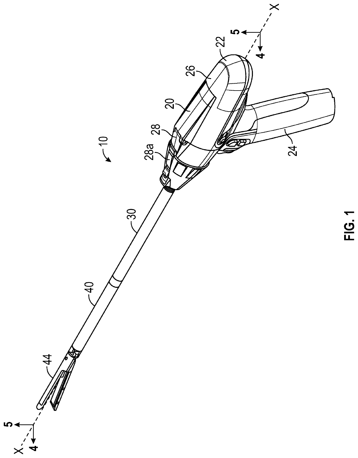
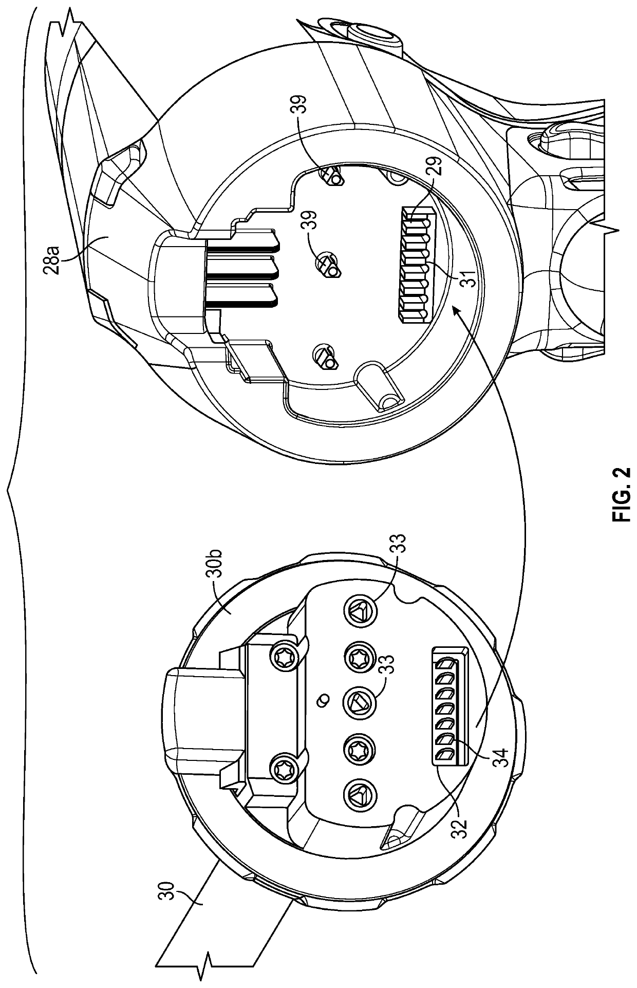
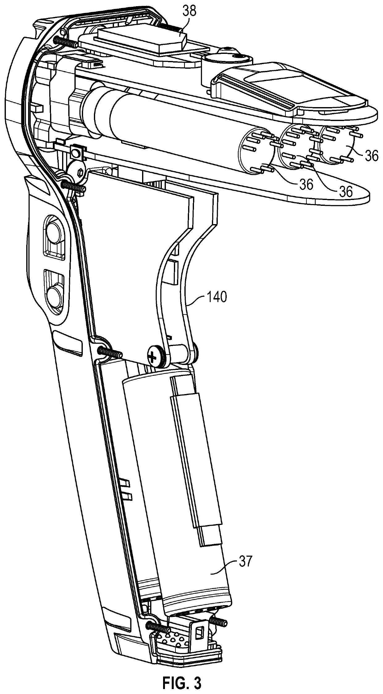
[0035]Embodiments of the present disclosure are now described in detail with reference to the drawings in which like reference numerals designate identical or corresponding elements in each of the several views. As used herein, the term “clinician” refers to a doctor, a nurse or any other care provider and may include support personnel. Throughout this description, the term “proximal” will refer to the portion of the instrument or component thereof that is closer to the clinician and the term “distal” will refer to the portion of the instrument or component thereof that is farther from the clinician. Additionally, in the drawings and in the description that follows, terms such as front, rear, upper, lower, top, bottom, and similar directional terms are used simply for convenience of description and are not intended to limit the disclosure. In the following description, well-known functions or constructions are not described in detail to avoid obscuring the present disclosure in unne...


PUM


Abstract

A surgical end effector includes an anvil assembly; a cartridge assembly including a plurality of fasteners; a drive assembly movable longitudinally to approximate the anvil assembly relative to the cartridge assembly; and a strain gauge circuit disposed within the cartridge assembly, the strain gauge circuit configured to measure a strain imparted on the cartridge assembly by the drive assembly.

Description

BACKGROUND[0001]This application claims the benefit of and priority to U.S. Provisional Patent Application Ser. No. 62 / 752,516 filed Oct. 30, 2018, the entire disclosure of which is incorporated by reference herein.BACKGROUND1. Technical Field[0002]The present disclosure relates to load sensing devices for use with surgical devices. More specifically, the present disclosure relates to load sensing devices used with electromechanical surgical systems for performing surgical procedures having reusable and single use components, such as end effectors and adapters.2. Background of Related Art[0003]Surgical fastener apparatuses for applying fasteners or staples to tissue are well known. These fastener apparatuses include single use instruments which are preloaded with one or more staples and are disposable after a single use. Multiple use instruments are also available and are preloaded with a plurality of staples. Multiple use instruments may include a handle assembly that is electromec...

Claims


Application Information

Patent Timeline
Patent Type & Authority Patents(United States)
IPC IPC(8): A61B17/072A61B90/00A61B17/00
CPCA61B90/06A61B17/07207A61B2017/0046A61B2017/07257A61B2017/07271A61B2090/064A61B2562/0261A61B2562/164A61B2017/0053A61B2017/00017A61B2017/0003A61B2017/00473A61B2017/00398
Inventor ESCHBACH, MATTHEW
Owner COVIDIEN LP
Learn More