Suspension device for cables and tubings

a suspension device and cable technology, applied in the direction of railway components, pipe supports, wagons/vans, etc., can solve the problems of cable carriers being quite expensive to purchase and install, not being able to choose to disconnect, and the solution suffering from some serious disadvantages, so as to reduce the risk of cables and tubings being damaged

Active Publication Date: 2021-12-28
FLEXIWAGGON AB
View PDF9 Cites 0 Cited by
  • Summary
  • Abstract
  • Description
  • Claims
  • Application Information

AI Technical Summary

Benefits of technology

[0007]An object of the present invention is to provide an improved, uncomplicated and inexpensive suspension device for cables and tubings extending between the load carrier and each bogie of a railway wagon, as presented in the introductory part, which will reduce the risk for the cables and tubings to become damaged. At least this object is achieved by a suspension device according to claim 1.
[0008]Accordingly, the basis of the invention is the insight that this object may be achieved by providing a suspension device on the underside of the ramp. The suspension device includes a guide arrangement extending transverse in relation to a longitudinal axis of the load carrier, along which guide arrangement a slider is displaceably movable. The slider is provided with a holder for holding of the one or more cables and / or tubings while at the same time allowing transverse movement of the cables and / or tubings together with the slider and holder along the guide arrangement. A suspension device designed in this way makes it possible to provide sufficient slack, i.e. sufficient long length of the cables and tubings to allow for the displacing of the load carrier during loading and unloading of vehicles without the risk for each of the cables and tubings to be teared apart, while at the same time prevent the cables and tubings to be dragged against the ground during transportation since they are lifted up by the ramp, which is raised while driving the train. Due to the guide arrangement and the slider, the bundle of cables and tubings will automatically be displaced to the one side of the ramp when the load carrier is displaced into its load and unload state, i.e. to the side of the ramp which is closest to the bogie. This allows to make the slack of the cables and tubings as short as possible and also reduces the risk for the cables and tubings to be damaged by being run over by a vehicle or squeezed between the outer end of the ramp and the ground since the bundle of cables and tubings will extend out at the side of the ramp and bridging the distance between the suspension device and the bogie.

Problems solved by technology

One problem with that kind of railway wagons is that the load carrier and the wheel bogies in each of its ends are electrically, hydraulically and pneumatically connected by means of electric cables and hydraulic and pneumatic tubings.
Therefore it is not an option to disconnect the cables and tubings each time a load carrier is displaced from its associated bogie or bogies, since then also a large number of the other railway wagons in the train set could be out of lightning, warming, cooling, braking effect, supply of hydraulic and pneumatic fluid for various other operations and the like.
There could for example be also other vehicle transporting wagons in the train set which are to be loaded or unloaded at the same time, which then would be impossible since the power supply via the cables and tubings is interrupted.
However, such a solution suffers from some serious disadvantages.
For one thing such cable carriers are quite expensive to purchase and install.
Moreover, these cable carriers have also turned out to be too sensitive for the exposed location between two railway wagons where they are exposed to dirt, rain, snow and ice formation, which may deteriorate its function to a large extent.
For example, when exposed to snow and ice formation, the interior channel of the cable carrier can be so filled with snow and ice such the cable carrier will open up when straightening and / or bending the cable carrier during displacing of the load carrier, with result that the cables and tubings may fall out from the cable carrier and run the risk of being damaged.

Method used


Image

  • Suspension device for cables and tubings
  • Suspension device for cables and tubings
  • Suspension device for cables and tubings

Examples


Embodiment Construction

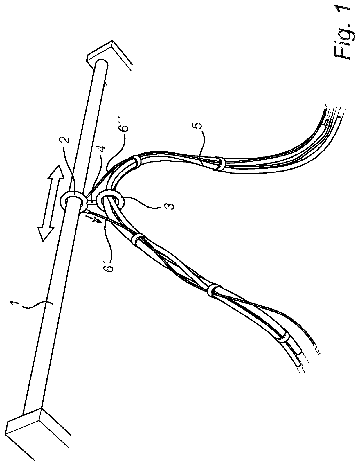
[0018]Reference is first made to FIG. 1 in which an embodiment of the inventive suspension device is illustrated in a perspective view from below. The suspension device comprises a guide arrangement in form of a rod 1 having a circular cross section, a slider 2 in the shape of a circular ring, which is slidably arranged on the guide rod 1, and a holder 3, also in the shape of a circular ring, which is rotatably connected to the slider 2 by means of a bolt 4 or the like. A bundle 5 of cables and tubings passes through the holder 3 such that they can move in their longitudinal direction through the holder. In order to protect the cables and tubings from tractive forces two traction wires are arranged and more precisely a first traction wire 6′, which is connected to the slider 2 in one end and a load carrier 7 (not shown in FIG. 1) in the other end, as well as a second traction wire 6″, which is connected to the slider 2 in its one end and a bogie 8 (not shown in FIG. 1) in the other ...


PUM


Abstract

The invention relates to a railway wagon comprising a load carrier (7) and front and rear bogies (8), each of the bogies being provided with railway track wheels and being electrically, hydraulically and / or pneumatically connected to the load carrier by means of one or more electric cables, hydraulic and / or pneumatic tubings (5). The load carrier is releasably connected to the respective bogies, and in a released state laterally displaceable in relation to the respective bogies by means of a displacement device. The load carrier has a front and a rear end and is at each end provided with a support device and a ramp (13), wherein the support device is adapted to support the load carrier on the ground in a position where it is displaced in relation to the bogie, whereas the ramp is along an inner edge pivotally connected to the end of the load carrier. The ramp is provided with a suspension device on the underside of the ramp including a guide arrangement (1) extending transverse in relation to a longitudinal axis of the load carrier, along which guide arrangement a slider (2) is displaceably movable, wherein the slider is provided with a holder (3) for holding of the one or more cables and / or tubings while allowing transverse movement of the cables and / or tubings together with the slider and holder along the guide arrangement.

Description

CROSS REFERENCE TO RELATED APPLICATIONS[0001]This application is the National Stage Entry under 35 U.S.C. § 371 of Patent Cooperation Treaty Application No. PCT / EP2015 / 079403, filed 11 Dec. 2015, the contents of which are hereby incorporated by reference in their entireties.FIELD OF THE INVENTION[0002]The present invention relates to a railway wagon comprising a load carrier and front and rear bogies, each of the bogies being provided with railway track wheels and being electrically, hydraulically and / or pneumatically connected to the load carrier by means of one or more electric cables, hydraulic and / or pneumatic tubings, the load carrier being releasably connected to the respective bogies, and in a released state laterally displaceable in relation to the respective bogies by means of a displacement device, the load carrier having a front and a rear end and being at each end provided with a support device and a ramp, the support device being adapted to support the load carrier on t...

Claims


Application Information

Patent Timeline
Patent Type & Authority Patents(United States)
IPC IPC(8): B61D47/00B61D3/04B61D3/18F16L3/015
CPCB61D47/005B61D3/04B61D3/187F16L3/015B61D3/182B61D3/184
Inventor ERIKSSON
Owner FLEXIWAGGON AB
Why Eureka
Try Eureka