Method for imaging a sample by means of a microscope and microscope

a technology of microscope and sample, applied in the field of method for imaging a sample by means of a microscope and a microscope, can solve the problems of insufficient illumination of the sample by means of the illumination unit, insufficient imaging lens system, and insufficient systematic error, etc., to achieve the improvement of the determination the effect of improving the accuracy of the brightness correction imag

Active Publication Date: 2022-01-04
CARL ZEISS MICROSCOPY GMBH
View PDF23 Cites 0 Cited by
  • Summary
  • Abstract
  • Description
  • Claims
  • Application Information

AI Technical Summary

Benefits of technology

[0013]Through the capture of the plurality of different areas, e.g. a systematically induced non-uniformity of the illumination can be determined in step e) and a corresponding brightness correction image can be provided. A correction of the non-uniformity of the illumination can thus be achieved in a simple manner.
[0015]With the method according to the invention, systematically induced inhomogeneities and / or undesired brightness variations in the captured image can thus be reduced.
[0016]In particular, an averaging of the values of the allocated image pixels of the reference images can be performed in step e) for the determination of the image pixel values of the brightness correction image. Such an averaging can be calculated easily and quickly and leads to good results.
[0019]Furthermore, it is possible, before step e), to separate out reference images which are over- or underexposed and not to take them into account in step e). The determination of whether an image is over- or underexposed can be performed in the usual manner. Thus, according to the invention, over- or underexposed images can be separated out and not taken into account in the determination of the image pixel values of the brightness correction image, with the result that the brightness correction image better reflects the systematic error of the illumination.
[0021]In particular, in the method according to the invention, the image sensor can have a linear detection range and only image pixels of the reference images the value of which lies in the linear detection range of the image sensor can be taken into account in step e). By the linear detection range of the image sensor would be meant in particular the range which leads to a linear increase in the measured value in the case of a linear increase in the brightness. The precision of the determination of the brightness correction image can be improved by this.
[0022]Furthermore, the images captured in step b) can be used continuously as reference images in step e). A continuous improvement in the determined brightness correction image is thus achieved. In this way, changes in the non-uniformity of the illumination over time can also be compensated for.

Problems solved by technology

There is often the difficulty that the illumination of the sample by means of the illumination unit is not optimum.
Thus a systematic error can remain which is reflected, e.g., in a non-uniform brightness distribution of the illumination over the sample.
Even the imaging lens system is often not optimum.
It can bring about an undesired inhomogeneity in the captured image.

Method used


Image

  • Method for imaging a sample by means of a microscope and microscope
  • Method for imaging a sample by means of a microscope and microscope
  • Method for imaging a sample by means of a microscope and microscope

Examples


Embodiment Construction

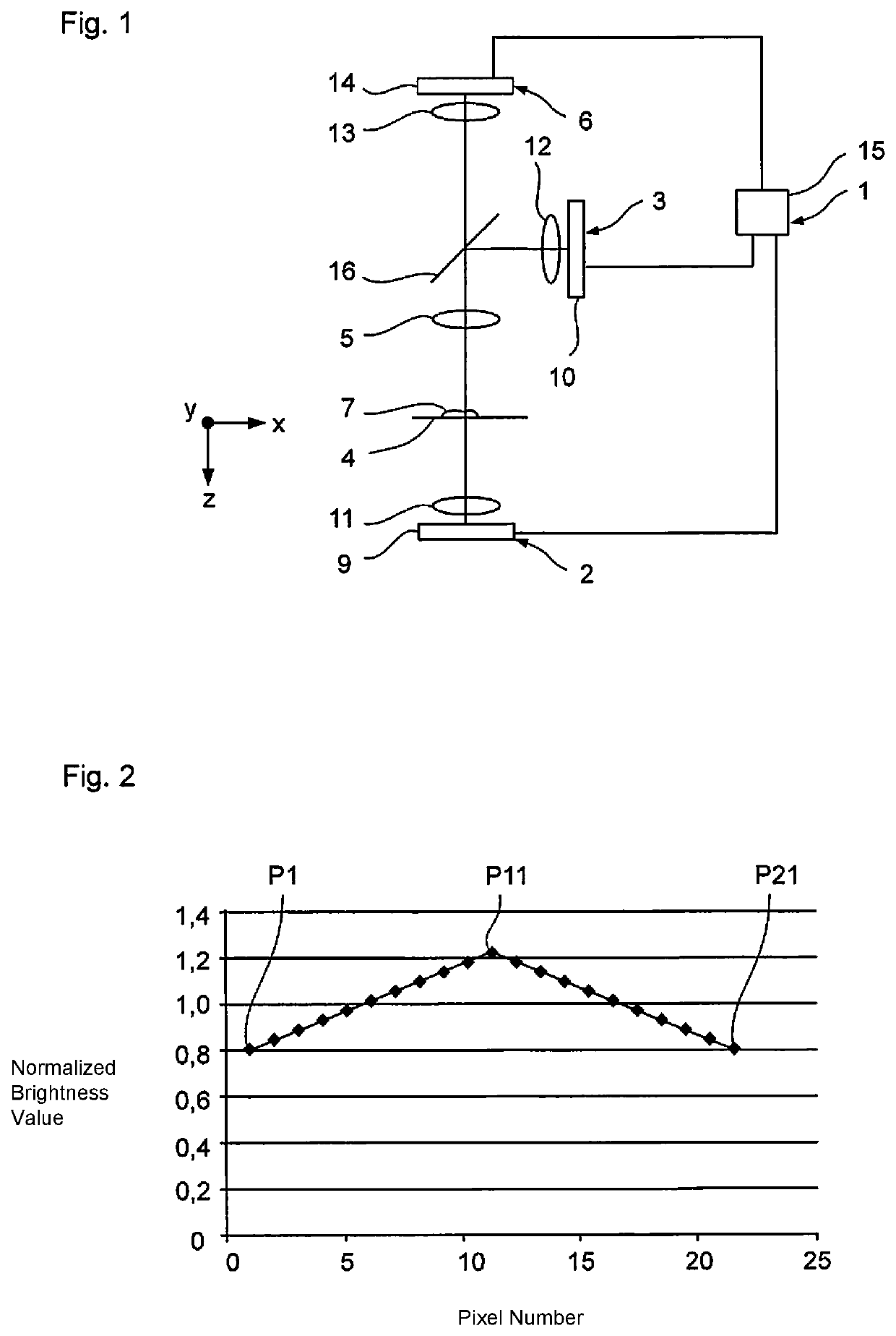
[0045]In the embodiment shown in FIG. 1, the microscope 1 according to an embodiment of the invention comprises a transmitted-light illumination unit 2, a reflected-light illumination unit 3, a sample stage 4, an imaging lens system 5, as well as a capture unit 6.

[0046]The microscope 1 can be operated as a transmitted-light microscope in which a sample 7 arranged on the sample stage 4 or an area of the sample 7 is illuminated from below by means of the transmitted-light illumination unit 2 and can be captured, magnified, from above by the capture unit 6 by means of the imaging lens system 5. By means of the capture unit 6 the desired image of the illuminated sample area can then be captured, wherein the captured image has a predetermined number of image pixels.

[0047]The microscope 1 can furthermore be operated as a reflected-light microscope in which the sample 7 arranged on the sample stage 4 or an area of the sample 7 can be illuminated from above by means of the reflected-light i...


PUM


Abstract

A method for imaging a sample using a microscope having an illumination unit, an imaging lens system and an image sensor, includes: illuminating an area of the sample; imaging and magnifying the sample onto the image sensor and capturing the image using a predetermined number of pixels; providing a plurality of different comparison sample areas; for each comparison sample area, performing a reference measurement, wherein the comparison sample areas are illuminated, imaged and magnified onto the image sensor and captured with the predetermined number of image pixels as a reference image; determining a brightness-correction image with the predetermined number of image pixels by determining the value for each image pixel of the brightness-correction image from the values of allocated image pixels of the reference images, and correcting the image of the area of the sample captured based on the brightness-correction image and outputting it as a corrected image.

Description

PRIORITY CLAIM[0001]The present application claims priority to German Patent Application No. 102014112002.7 filed on Aug. 21, 2014, which said application is incorporated by reference in its entirety herein.FIELD OF THE INVENTION[0002]The present invention relates to a method for imaging a sample by means of a microscope as well as a microscope.BACKGROUND[0003]In a method for imaging a sample by means of a microscope which has at least an illumination unit, an imaging lens system and an image sensor, for the imaging, an area of the sample can be illuminated with illumination radiation by means of the illumination unit, and the illuminated sample area can be imaged, magnified, onto the image sensor by means of the imaging lens system and an image of the illuminated sample area can be captured with a predetermined number of image pixels.[0004]There is often the difficulty that the illumination of the sample by means of the illumination unit is not optimum. Thus a systematic error can ...

Claims


Application Information

Patent Timeline
Patent Type & Authority Patents(United States)
IPC IPC(8): G02B21/00G02B21/16G02B21/36H04N5/235G06T5/50G02B21/06G06K9/62H04N5/232H04N5/243
CPCG02B21/008G02B21/0032G02B21/0044G02B21/0084G02B21/06G02B21/16G02B21/365G06K9/6201G06T5/50H04N5/235H04N5/2351H04N5/2352H04N5/2354H04N5/2356H04N5/23296H04N5/243G06F18/22H04N23/69H04N23/70H04N23/71H04N23/72H04N23/74H04N23/76H04N23/743
Inventor HEUPEL, THORSTEN
Owner CARL ZEISS MICROSCOPY GMBH
Why Eureka
Try Eureka