Supercharge Your Innovation With Domain-Expert AI Agents!

Method for the production of hollow chamber valves

a hollow valve and chamber technology, applied in the direction of lift valves, engine components, machines/engines, etc., can solve the problems of high cost of turning or milling the cavity, and many process steps are often necessary

Active Publication Date: 2022-03-01
FEDERAL MOGUL VALVETRAIN GMBH
View PDF11 Cites 2 Cited by
  • Summary
  • Abstract
  • Description
  • Claims
  • Application Information

AI Technical Summary

Problems solved by technology

In particular turning or milling of the cavity is costly.
Another disadvantage of known methods is that a large number of process steps are often necessary.

Method used


Image

  • Method for the production of hollow chamber valves

Examples


Embodiment Construction

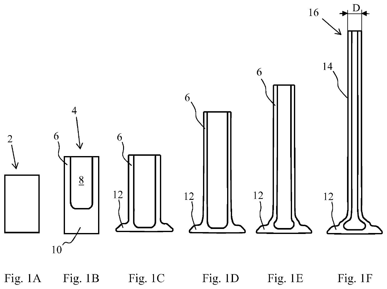
[0018]FIGS. 1A through 1F show sectional views of intermediate steps of the manufacturing method according to an embodiment of the invention. A blank 2 made of a valve steel known to those skilled in the art is preferably used as the starting point (see FIG. 1A). The blank has an at least partially cylindrical shape, preferably a circular cylindrical shape, corresponding to the circular shape of the valve body or valve to be manufactured.

[0019]The blank 2 is formed into a bowl-shaped semi-finished product 4 or workpiece illustrated in FIG. 1B. The semi-finished product in the form of a bowl includes a base section 10, from which a valve head (or valve disk) 12 is subsequently formed, and an annular wall 6 that surrounds a cylindrical, preferably circular cylindrical, cavity 8 of the bowl-shaped semi-finished product 4, and from which a valve stem 14 is subsequently formed. In this regard, any material may flow between the base section 10 and the annular wall 6 during the subsequent ...


PUM

PropertyMeasurementUnit
outer diameteraaaaaaaaaa
diametersaaaaaaaaaa
thermalaaaaaaaaaa

Abstract

Disclosed is a method for the production of a valve body of a hollow chamber valve, said method comprising: providing a bowl-shaped semi-finished product having an annular wall, which surrounds a hollow chamber, and a bottom portion, followed by a lengthening of the wall and a final reducing of an outer diameter of the annular wall in order to obtain a predetermined valve shaft outside diameter of a valve that is to be produced. Further disclosed is a hollow chamber valve produced by means of said method.

Description

BACKGROUND1. Technical Field[0001]The present invention relates to a method for manufacturing hollow valves for an internal combustion engine, and hollow valves manufactured using the method.2. Related Art[0002]Intake valves and exhaust valves are components in internal combustion engines that are subject to high thermal and mechanical stress. Therefore, sufficient cooling is necessary to ensure long-term functionality of the valves. Compared to solid stem valves and hollow stem valves, hollow valves are advantageous due to the fact that a cavity is present in both the stem and the valve head, as the result of which improved internal cooling, using a coolant such as sodium, may be achieved. Further advantages are lower weight, avoidance of hot spots, and reduced CO2.[0003]Hollow valves are typically manufactured by a combination of various processes such as forging, turning, and welding. In particular turning or milling of the cavity is costly. In addition, weld spots on the disk su...

Claims


Application Information

Patent Timeline
Patent Type & Authority Patents(United States)
IPC IPC(8): B21K1/22B21C23/20
CPCB21K1/22B21C23/205F01L2303/00F01L3/14
Inventor MATTHIAS, THORSTENWOLKING, ANTONIUSBAYARD, GUIDOHEINEK, ANDREAS
Owner FEDERAL MOGUL VALVETRAIN GMBH
Features
  • R&D
  • Intellectual Property
  • Life Sciences
  • Materials
  • Tech Scout
  • Unparalleled Data Quality
  • Higher Quality Content
  • 60% Fewer Hallucinations
Learn More